background image

31

Step 11.   Lighting the Appliance

STANDING PILOT IGNITION

A. This appliance (standing pilot version) has a pilot

that must be lighted by hand. When lighting the
pilot, follow these instructions exactly.

B. BEFORE LIGHTING smell all around the appli-

ance area for gas. Be sure to smell next to the
floor because some gas is heavier than air and
will settle to the floor.

WHAT TO DO IF YOU SMELL GAS

• Do not try to light any appliance.

• Do not touch any electric switch; do not use any

phone in your building.

• Immediately call your gas supplier from a neigh-

bor’s phone. Follow the gas supplier’s instruc-
tions.

• If you cannot reach your gas supplier, call the fire

department.

C. Use only your hand to push in or turn the gas

control knob. Never use tools. If the knob will not
push in or turn by hand, don’t try to repair it, call
a qualified service technician. Force or attempt-
ed repair may result in a fire or explosion.

D. Do not use this appliance if any part has been

under water. Immediately call a qualified service
technician to inspect the appliance and to replace
any part of the control system and any gas con-
trol which has been under water.

FOR YOUR SAFETY

READ BEFORE LIGHTING

WARNING: IF YOU DO NOT FOLLOW THESE
INSTRUCTIONS EXACTLY, A FIRE OR
EXPLOSION MAY RESULT CAUSING
PROPERTY DAMAGE, PERSONAL INJURY, OR
LOSS OF LIFE.

1.

To access controls, open the lower grille.

2.

Turn the gas control valve knob to the OFF position. To do this, you
must turn the knob clockwise

 to the PILOT position, and then

press in and continue turning clockwise

  to the OFF position.

NOTE:

Knob cannot be turned from “PILOT” to “OFF” unless knob is

pushed in slightly. Do not force.

3.

WAIT AT LEAST FIVE (5)  MINUTES TO CLEAR OUT ANY GAS.  If
you have unsuccessfully tried to light the fireplace, wait longer, espe-
cially if you are using LP gas.  Then smell for gas, including near the
floor. If you then smell gas,

STOP!

  Follow "B" in the safety informa-

tion on  previous page. If you don't smell gas, go to the next step.
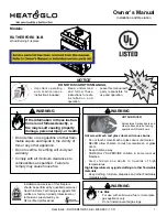
4.

The pilot should not require accessing for light-
ing purposes. The pilot is located inside the com-
bustion chamber. If it is necessary to access
the pilot, remove the trim door and glass door.

                                THERMOCOUPLE

                                               PILOT

                                    THERMOPILE

5.

To put the control in the PILOT position, turn the control knob counter-
clockwise

  to the  PILOT position.

6.

To light the pilot press the control knob and then press the red or black
piezo button once every second.  The piezo makes a clicking sound.  It
may be necessary to repeat this step. If the pilot does not light after
10 seconds, go back to step 2.  The control knob should be held down
for a MINUTE after pilot ignition.

• If the control knob does not pop out when released, 

STOP!

Shut off

the gas supply to the fireplace control valve, and 

IMMEDIATELY

call

your service technician or gas supplier.

• If the pilot will not stay lit after two tries, turn the control knob to the

“OFF” position and call your service technician or gas supplier.

7.

After the pilot has been lit, the burner can be turned on by turning the
knob counter-clockwise

 to the “ON” position.

8.

Set the ON/OFF switch to the “ON” position.

9.

Close the lower grille.

LIGHTING INSTRUCTIONS

STANDING PILOT CONTROLS

TO TURN OFF

GAS APPLIANCE

1.

Open the lower grille.

2.

Set ON/OFF switch to “OFF”.

3.

Turn the valve control knob clockwise

 to the “Pilot” position,

then depress knob and continue turning to “OFF” position.

4.

Close the lower grille.

When you light your fireplace, you may notice:

This gas appliance produces heat which does have an asso-
ciated odor or smell. If you feel this odor is excessive it may
require the initial 3-4 hour continuous burn on high followed
by a second burn up to 12 hours to fully drive off any odor
from paint and lubricants used in the manufacturing process.
During this break-in period it is recommended that some win-
dows in the house be opened for air circulation. This will help
avoid setting off smoke detectors, and help eliminate any

odors associated with the fireplace’s initial burning.

Additionally, for the first few minutes after each lighting, va-
por may condense and fog the glass and flames may be
blue.  After a few minutes this moisture will disappear and
within 15-30 minutes the flames should become yellow.

Noise caused by metal expanding and contracting as it heats
up and cools down, similar to the sound produced by a
furnace or heating duct. This noise does not affect the op-
eration or longevity of your fireplace.

You’ve reviewed all safety warnings, you’ve checked the
appliance for gas leaks, you know the vent system is

unobstructed, and you’ve checked for faulty components.
Now you’re ready to light the appliance.

‹

Summary of Contents for QV36D

Page 1: ...CE FOR FUTURE REFERENCE 1 This appliance may be installed in an af termarket permanentlylocated manufac tured mobile home wherenotprohibited by local codes 2 This appliance is only for use with the ty...

Page 2: ...instructions may result in a possible fire hazard and will void the warranty Prior to the first firing of the fireplace READ the Using Your Fireplace section of the Owners Guide DO NOT USE this applia...

Page 3: ...9 C Vent Termination 23 Step 4 Positioning Leveling and Securing the Fireplace 26 Step 5 The Gas Control Systems 26 Step 6 The Gas Supply Line 27 Step 7 Gas Pressure Requirements 27 Step 8 Wiring the...

Page 4: ...odes or in the absence of local codes with the National Electric Code ANSI NFPA No 70 in the United States or to the CSA C22 1 Canadian Electric Code in Canada This model may be installed in a bedroom...

Page 5: ...will void the own er s warranty and may present a fire hazard Getting Started The Hearth Home Technologies Warranty will be voided by and Hearth Home Technologies disclaims any responsibility for the...

Page 6: ...5 8 219mm VENT COLLARS ELECTRICAL ACCESS 26 7 8 682mm 12 3 4 323mm 3 1 2 90mm GAS LINE ACCESS 2 1 8 55mm 6 7 8 174mm 14 1 4 362mm 8 5 8 219mm VENT COLLARS 21 1 2 548mm 11 5 8 297mm 28 1 2 724mm TOP S...

Page 7: ...TRUCTIONS ARE NOT SUBSTITUTES FOR THE REQUIREMENTS OF LOCAL BUILDING CODES THEREFORE YOUR LOCAL BUILD ING CODES MUST BE CHECKED TO DETERMINE THE REQUIREMENTS FOR THESE STEPS Factory built fireplace ch...

Page 8: ...ION MEASURE FIREPLACE DIMENSIONS AND VERIFY FRAMING METHODS AND WALL COVERING DETAILS BEFORE FRAMING 1 2 CLEARANCE FROM BACK OF FIREPLACE TO COMBUSTIBLE 0 CLEARANCE TO FRAMING MEMBER 0 CLEARANCE 1 2 C...

Page 9: ...h outer pipe DV 36D 5 3 4 146mm 8 3 4 222mm 11 3 4 298mm DV 48D 7 3 8 187mm 6 5 32 156mm 11 5 8 295mm 8 5 8 220mm 8 1 2 216mm 6 7 16 164mm 11 1 16 281mm 6 1 2 165mm 8 1 2 216mm 5 1 16 129mm 8 5 8 220m...

Page 10: ...g configuration used Terminations Kits HORIZONTAL TERMINATION WALL FIRESTOP 90 DEGREE ELBOW VERTICAL TERMINATION STORM COLLAR ROOF FLASHING HORIZONTAL PIPE SUPPORT PIPE LENGTH WALL BRACKET CEILING FIR...

Page 11: ...the four screws securing it in place see Figure 7 Figure 8 Flue Restrictor BREAK HERE Figure 7 EXHAUST SHIELD FLUE RESTRICTOR 2 Break the Flue Restrictor into two pieces Do this by bending the part b...

Page 12: ...3 Match the amount of vertical you have in the sys tem with the chart to find the appropriate position to set the Flue Restrictor 1 2 3 4 5 SETTINGS 1 2 3 4 5 Figure 9 CHART Vertical Top Vent NG Top...

Page 13: ...1 MIN 305mm 2 MAX 610mm 2 MIN 610mm 4 MAX 1 22m 3 MIN 914mm 6 MAX 1 86m 4 MIN 1 22m 8 MAX 2 4m V H 40 MAX 12 4m H 8 MAX 2 4m NOTE On vertical venting configurations where the vertical component is ov...

Page 14: ...1 20 MAX 6 2m V V1 H 40 MAX 12 4m Figure 14 Venting with Two 90 Elbows VENTING WITH TWO 2 90 ELBOWS V H H H1 1 MIN 305 mm 2 MAX 610 mm 5 MAX 1 52m 2 MIN 610 mm 4 MAX 1 22 m 10 MAX 3 1m 3 MIN 914 mm 6...

Page 15: ...914mm 6 MAX 1 86m 15 MAX 4 65m 4 MIN 1 22m 8 MAX 2 48m 20 MAX 6 2m V H H1 H2 40 MAX 12 4 m H 8 MAX 2 48 m H H 1 H2 20 MAX 6 2 m V H H H1 H2 1 MIN 305mm 2 MAX 610mm 5 MAX 1 52m 2 MIN 610mm 4 MAX 1 22m...

Page 16: ...IN 914mm 15 MAX 4 65m 4 MIN 1 22m 20 MAX 6 2m NOTE H H1 20 MAX 6 2m V V1 H H1 40 MAX 12 4m V FT H H1 FT 1 MIN 305mm 5 MAX 1 52m 2 MIN 610mm 10 MAX 3 1m 3 MIN 914mm 15 MAX 4 65m 4 MIN 1 22m 20 MAX 6 2m...

Page 17: ...YOU ARE NOT USING If your vertical vent component is over 10 feet you may want to install the included vertical baffle to improve flame appearance Vertical baffle is located in the bag containing the...

Page 18: ...ion with the pre ceding component attach with a minimum of two 2 sheet metal screws Figure 20 CORRECT INCORRECT 2 Fasten the shield in place using the pilot holes provided in the part The shield shoul...

Page 19: ...The center of the hole is one 1 inch 25 4mm above the center of the horizontal vent pipe Position the firestops on both sides of the hole previ ously cut and secure the firestops with nails or screws...

Page 20: ...11 inch 280mm X 280mm hole through the ceiling using the centerpoint previously marked Frame the hole with framing lumber the same size as the ceiling joists Figure 27 Ceiling Firestop Ceiling Side If...

Page 21: ...NATION CAP MUST BE POSITIONED SO THAT THE ARROW IS POINTING UP Using screws secure the cap to the exterior wall through the flanges in the cap Figure 29 Trapezoid Termination Cap WARNING THE BOTTOM OF...

Page 22: ...IS STRONGLY RECOMMENDED WHENEVER POSSIBLE TO USE THE VINYL PROTECTOR KIT 30 minimum for vinyl clad soffits a vent shall not terminate directly above a sidewalk or paved driveway which is located betw...

Page 23: ...SEE FIGURE 31 FOR MINIMUM HEIGHTS PROVIDED THE TERMINATION CAP IS AT LEAST TWO 2 FEET FROMAVERTICAL WALL AND 2 FEET BELOW AHORIZONTAL OVERHANG NOTE This also pertains to vertical vent systems in stall...

Page 24: ...o properly position level and secure the fireplace Figure 32 Proper Positioning Leveling and Securing of a Fireplace Figure 33 Gas Control System STANDING PILOT Step 5 The Gas Control System WARNING T...

Page 25: ...r and it does not penetrate the actual firebox Open the fireplace lower grille insert the gas supply line through the gas line hole and connect it to the shut off valve When attaching the pipe support...

Page 26: ...ll Run a maximum of 25 feet 7 8 m or less length of 18 A W G minimum wire and connect it to the fireplace ON OFF switch pigtails WARNING DO NOT CONNECT 110 120 VAC TO THE WALL SWITCH OR THE CONTROL VA...

Page 27: ...TWEEN THE FINISHED WALLS AND THE FIREPLACE SURROUND TOP AND SIDES ARE SEALED A 300 F MINIMUM SEALANT MATE RIAL MUST BE USED THESE JOINTS ARE NOT RE QUIRED TO BE SEALED ONLY NON COMBUSTIBLE MATERIAL US...

Page 28: ...he bag of embers provided is sufficient for 3 to 5 applications Replace the glass door and a front trim door on the unit Pull out and latch the glass clips into the groove on the glass frame Aladdin H...

Page 29: ...e control in the PILOT position turn the control knob counter clockwise to the PILOT position 6 To light the pilot press the control knob and then press the red or black piezo button once every second...

Page 30: ...selves of this air Once the purging is complete the fireplace will light and will operate normally Subsequent lightings of the fireplace will not require this purging of air from the gas supply lines...

Page 31: ...urrounding the logs Checking Flame Patterns Flame Height Frequency Periodically By Qualified service technician Home owner Task Make a visual check of your fireplace s flame patterns Make sure the fla...

Page 32: ...he pilot and hold the valve knob in If the millivolt reading is less than 15mV replace the thermocouple b Defective valve If the thermocouple is producing more than 15 millivolts replace faulty valve...

Page 33: ...downwards lope is 1 4 inch d Glass too loose and air tight packet leaks in corners after usage Tighten the corner e Bad thermopile or thermocouple Replace if necessary f Improper vent cap installation...

Page 34: ...ssories Adjustments regular maintenance cleaning and temporary repairs do not qualify for a service call fee and will not be covered The replacement of consumer replaceable items and installation of u...

Reviews: