


0478 111 9921 A - EN
40
●
Fit the upper handlebar (1) onto the
lower handlebar sections (2).
●
Insert all cables into the anti-kink cable
protection (3). Insert flat head bolts (E)
through bores from the inside to the
outside.
Attach anti-kink cable protection (3)
only as shown. Cables must be routed
under the handlebar.
●
Fit washers (F) onto the bolts and
screw on the cap nuts (G) (22 - 28 Nm).
Check the hook-and-loop fasteners.
●
The cables must be fastened to the
right and left upper handlebars using
hook-and-loop fasteners (4) as shown.
Correct the position of the hook-and-
loop fasteners if necessary.
Folding down the upper handlebar:
The upper handlebar (1) can be folded
down for space-saving transport and
storage of the mower.
●
Screw off cap nuts (G) on both sides
and remove together with the
washers (F).
●
Fold down the upper handlebar (1)
forwards and rest it on the engine hood.
8.2 Assembling grass catcher
bag
●
Pull the grass catcher bag
fabric (C) over the grass catcher bag
frame (B) as shown. The struts (1) and
the handle (2) must be located on the
outside of the fabric.
●
Position the integrated plastic
sleeves (3) on the grass catcher bag
frame and press them into place. Start
by pressing under the tab of the grass
catcher bag frame.
●
First attach the flap (D) on the left, then
on the right of the catcher bag frame,
then snap them in on both sides by
pressing firmly.
8.3 Attaching the recoil starter
rope
●
Detach the spark plug socket
from the engine.
●
Slowly pull out the recoil starter rope (1)
and attach it to the rope holder (2).
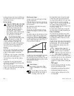
8.4 Lateral adjustment of the
handlebar
The handlebar can be adjusted
laterally to enable more comfortable
mowing on slopes or along fences, hedges
and walls.
●
Release the handlebar clamp by
opening the tension lever (1).
●
Hold the handlebar (2) by the handles
and lift slightly. Then turn it to the left or
right until it is in the desired position.
The handlebar engages noticeably in
the left and right position, as well as in
the centre position.
●
Close the tension lever (1) again to lock
the handlebar in place.
8.5 Height adjustment of the
handlebar
The height of the handlebar is
adjustable to three positions:
●
Release the rotary handle (1) (approx.
5 turns anti-clockwise).
●
Hold the handlebar (2) at the handles
with both hands and bring to the desired
position – ensure same adjustment on
left and right side.
●
Tighten the rotary handle (1) again.
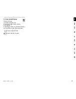
8.6 Central cutting height
adjustment
Seven
different cutting heights can
be set between
30 mm
and
85 mm
.
Level
1
= lowest cutting height
Level 7
= highest cutting height
Danger of pinching!
The upper handlebar (1) can fold
down on its own when the two cap
nuts (G) are loosened. Therefore
hold the upper handlebar (1) at its
highest point before loosening the
two cap nuts.
4
5
6
I
Low
II
Medium
III
High
7
8
Summary of Contents for MB 750 KS
Page 2: ...0478 111 9921 A M0 39 F14 Ess Printed in Germany 2014 VIKING GmbH A 6336 Langkampfen Kufstein ...
Page 3: ...1 0478 111 9921 A 1 2 ...
Page 4: ...0478 111 9921 A 2 3 ...
Page 5: ...3 0478 111 9921 A 4 5 6 7 8 ...
Page 6: ...0478 111 9921 A 4 9 10 11 12 13 14 ...
Page 7: ...5 0478 111 9921 A 15 16 17 18 19 20 ...
Page 8: ...0478 111 9921 A 6 21 22 23 24 25 ...
Page 9: ...7 0478 111 9921 A 26 ...
Page 10: ...0478 111 9921 A 8 ...
Page 32: ...0478 111 9921 A DE 30 ...
Page 52: ...0478 111 9921 A EN 50 ...
Page 138: ...0478 111 9921 A ES 136 ...
Page 204: ...0478 111 9921 A HU 202 ...
Page 208: ...0478 111 9921 A RU 206 16 Э VIKING VIKING ...
Page 209: ...207 DE EN FR NL IT ES PT PL HU RU 0478 111 9921 A RU 5 2 4 5 3 5 4 ...
Page 210: ...0478 111 9921 A RU 208 Ö 14 5 5 VIKING Ö 12 5 VIKING VIKING 5 6 ...
Page 211: ...209 DE EN FR NL IT ES PT PL HU RU 0478 111 9921 A RU Ö 11 Ö 11 1 25 46 6 25 46 6 100 Э ...
Page 212: ...0478 111 9921 A RU 210 VIKING VIKING ...
Page 214: ...0478 111 9921 A RU 212 VIKING 5 8 5 9 VIKING VIKING ...
Page 228: ...0478 111 9921 A RU 226 20 2 VIKING 26 ...
Page 229: ...www viking garden com 04781119921A 0478 111 9921 A ...