Viking E-60-BK-IP Product Manual Download Page 8

PC Requirements

•  IBM 

compatible personal computer with:

Windows 2000 (service pack 4 or higher)
Windows XP (service pack 2 or higher)
Windows Vista (SP2 or newer), 32 or 64 bit versions
Windows 7
         Windows 8

•  

Adobe Acrobat Reader 8 or higher

•  E-60-IP

hardware

•  

Available LAN with PoE (class 1, <4 watts)

•  

Ethernet cable ( CAT5 min.)

•  

1 MB minimum free hard drive space for installation

•  16MB of free physical RAM

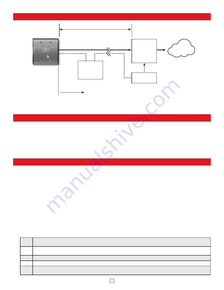
Typical Installation on SIP Based VoIP Phone System

Optional

PoE Injector

(If VoIP PBX does 

not have PoE)

Optional 

Switch / Hub

(Extends range of cable, keeps 

1 Gbps network speed for other 

equipment on network)

SIP VoIP PBX

or

PC with

SIP Server

Software

100m (328 ft) max*

Viking 

supplies

Customer’s 

Responsibility

Internet

10/100 Mbps

Maximum

Viking

E-60-SS-IP

Entry Phone

* Note: 

A PoE extender can be used for an additional 100 meters per extender. For longer runs (up to 2 km / 1.2 miles) 

a ethernet to fiber media converter can be used.

PC Programming

A DVD is included with each 

E-60-IP

VoIP  Entry phone. The DVD contains the application “

Viking VoIP Phone Programming

” used to

program the unit using a PC running Windows 2000, XP, Vista, Windows 7, or Windows 8 (see System Requirements above). The PC must
be connected to the same LAN as the 

E-60-IP

VoIP phone. Install the application on your PC by placing the DVD into your PC’s drive. Click

“I Accept” on the bottom of the first screen, then select “Viking VoIP Phone Programming” and click the “Install” button. Follow the directions
on the screen. If you are reinstalling the Viking VoIP Phone Programming software you must uninstall the original version first via “Add and
Remove Programs”. To start the Viking VoIP Phone Programming application, click on the Viking VoIP Phone Programming icon on your desk
top. The Main screen will appear, allowing the user to program any 

E-60-IP

phone connected to that LAN.   

A. Manually Muting SIP/Network Failure Alarm Beeps

(3 beeps repeated every 30 seconds)

With the unit connected and powered (Green LED on and Yellow LED off or blinking) it will output 3 beeps every 30 seconds and
turn the Call/Call Connected LED on and off once per second indicating a SIP registration failure, failure to receive an echo reply
from pinged gateway or Ethernet connection failure. You can manually disable the beeps by pressing and holding the Call button for
5 seconds (2 beeps will then be heard) or by clicking the “Mute Alarm Until Next Failure” tab in the Viking VoIP programming software.
The LED will continue to flash allowing you to trouble shoot the failure.

B.  Configuring the E-60-IP Network Settings

Step 1.

Open the “Viking VoIP Phone Programming” software on a windows PC that is connected to the same LAN as the 

E-60-IP

phone to be

programmed. 

Step 2.

The window in the upper left corner of the menu will show you each 

E-60-IP

phone that is connected to that LAN. Select the unit with

the same MAC address shown on the label located on the top of the Ethernet connector on the 

E-60-IP

phone.

Step 3.

Click the “Connect” button. If a pop up window appears, enter the unit’s security code (factory set to 

845464

) then click the “OK” button.

Step 4.

The program will then read and display the 

E-60-IP

phone’s IP and programming settings.

Step 5.

After adjusting the IP and phones settings, click the “Write” button under each column of settings to send the programming commands
to the connected unit.

8

Summary of Contents for E-60-BK-IP

Page 1: ...875 x 4 938 x 0 17 Phone 72mm x 46mm x 42mm 2 84 x 1 8 x 1 65 Shipping Weight 0 55 kg 1 2 lbs Operating Temperature 40 C to 60 C 40 F to 140 F Humidity Standard Products 5 to 95 non condensing Humidit...

Page 2: ...vice Provider 3COM VCX X 3CX X Aastra X Asterisk X Atcom X Avaya IP Office X BlueBox X Brekeke X Callcentric X Cisco Unified Communications Manager CUCM X X Cisco Unified Communications Manager Expres...

Page 3: ...otocol is an Internet protocol standard that specifies a way for programs to manage the real time transmission of multimedia data over either unicast or multicast network services Server A computer or...

Page 4: ...oller etc not connected Push Button Switch Push to initiate call push again to disconnect Solid 316 stainless steel internally sealed per IP67 Speaker Screen Speaker screen with 0 018 wide slots to pr...

Page 5: ...n mounting to vinyl siding Step 3 Cut a hole through the siding and wall sheathing just large enough for the rough in box Caution Too large of a hole can cause plate misalignment and compromise the ga...

Page 6: ...ional VE 5x5 Surface Mount Box with black satin powder paint finish not included DOD 424 Optional VE LIGHT kit can be used to illuminate the faceplate when used with a VE 5x5 DOD 428 WARNING Do NOT us...

Page 7: ...tors for use when replacing E 60 EWP circuit boards Optional 2 Amp Relay Output Contacts Connector Connect to doorstrike mag lock gate controller etc 3 1 10 1 Step 1 Cut wires from J1 10 pin connector...

Page 8: ...nal version first via Add and Remove Programs To start the Viking VoIP Phone Programming application click on the Viking VoIP Phone Programming icon on your desk top The Main screen will appear allowi...

Page 9: ...n the E 60 IP phone answers enter the 6 digit security code factory set to 845464 see section B A double beep should then be heard indicating you have entered the programming mode Step 3 You can now t...

Page 10: ...digits 24 Relay Activation Time 2 digits 00 99 sec 00 0 5 sec factory set to 05 2 digits 00 99 25 Relay Mode 0 Door Strike 1 Outbound Call 2 In Outbound Call 3 Doorbell 4 LV 1K Control 5 Ring 6 Ring...

Page 11: ...ation number 00 04 To clear a speed dial location simply enter the memory location 00 04 alone The E 60 IP phone is factory set with no speed dial number pro grammed To Program Enter Q QQ Q 0 1 2 9 0...

Page 12: ...sy is detected the E 60 IP phone will dial the next programmed speed dial number and continue to cycle through the numbers until a call is com pleted Notes This feature is enabled in the factory defau...

Page 13: ...m the Entry phone This mode is useful for activating strobe lights for Emergency VoIP phones 2 Inbound Outbound Call Mode When programmed for Inbound Outbound Call Mode the relay will activate continu...

Page 14: ...of the following three modes 0 OFF Silent Monitoring Mode In the OFF mode the speaker is disabled at all times However the speaker can be enabled after communication has been established by entering t...

Page 15: ...tion Activate Relay QQ or ___ ___ Momentarily activate relay 1 or 2 digits factory set to QQ Un Latch Relay Q0 Un latch deactivate the relay Latch Relay Q1 Latch continuously activate the relay Discon...

Page 16: ...ications Note The VE 3x5 is not compatible with the VE GNP pedestals The VE PNL s are VE Series backboxes with a blank aluminum panel The user can customize the clear coated aluminum panel to mount an...

Page 17: ...EAR LIMITED WARRANTY Viking warrants its products to be free from defects in the workmanship or materials under normal use and service for a period of two years from the date of purchase from any auth...

Reviews: