background image


  21 

VIGAS 18 DPA, VIGAS 26 DPA  

Gasifying boilers VIGAS


10.2 MODULE SETTINGS AK 4000M


10.3 SERVICE CONTROL FUNCTIONS


10.4 HYDRAULIC SCHEMA SETTING 


By modification of hydraulic schema connection will also be changed the control of the pump output and 
boiler  configuration.  Therefore,  it  is  very  important  that  software  settings  for  the  hydraulic  schematic  is 
identical  with  existing  boiler  installation  in  the  central  heating  system. In the  basic  memory  of  the  control 
unit are 5 basic schemas and schemas intended for operating with the Expander AK4000E. On demand, it 
is  possible  to  add  Expander  schemes  via  AK4000M  module  (pic.8).  Updated  schemas  for  Expander 
AK4000E can be found on 

www.vigas.eu


When  necessary,  it  is  possible  to  connect  AK4000  control  to  the  module  AK4000M  (pic.8).  This  module 
allows  to  upgrade  and  backup  data  maintenance  of  the  boiler  control  unit.  The  module  is  equipped  with 
data to make it possible to connect to BH BUS power board and USB to the PC. 

config


To  load  a  new  configuration  (connection  schematic). 
Mainly  used  for  systems  controlled  by  EXPANDER 
AK4000E,  where  it  is  possible  to  load  personal 
connection schematics.


config


Currect  configuration  back-up.  It  is  used  for  boiler 
monitoring. It is advised to perform before monitoring.


f

irmware


To load firmware (boiler operating software).    


Erase


To delete information from module AK4000M. 

mon


Boiler  monitoring  -  to  save  basic  information  of  the 
boiler  into  memory  module


AK4000M.  Before 

monitoring  it  is  necessary  to  backup  current 

configuration 

config. 

Data is saved every 3s. Data 

control will be realized by producer.


AK4000S 

To download firmware into the power board AK4000S 

AK4000EP 

To download firmware to pellet expander AK4000EP 


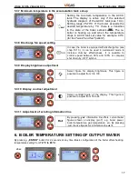
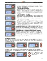
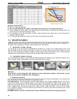
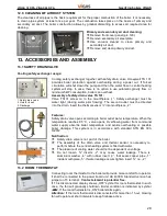
In  service  settings  the  functions  of  each  boiler‘s  components  can  be  checked  according  to  the  symbols 
indicated  on  the  display.  By  selecting  component  and   pressing  „ENTER“  button  the  function  will  be 
activated. Displayed components depend on the boiler‘s configuration. 

2x 

pic.8

Summary of Contents for 18 DPA

Page 1: ...AS 18 DPA VIGAS 26 DPA Gasifying boilers VIGAS Gasifying boilers MANUAL FOR INSTALLATION ASSEMBLY MAINTENANCE AND USE Warranty Certificate VIMAR 2017 Ver D 2 00 VIGAS 18 DPA VIGAS 26 DPA with AK4000 control ...

Page 2: ...ture setting 7 Time setting 8 Hardware and software information 9 Error notification 10 Configuration set up using PIN 0000 11 Operating instruction 12 Boiler maintenance and repairs 13 Boiler accessories and assembly 14 List of servise centers 15 Problems causes and solutions 16 Installation instructions 17 Wiring diagram Warranty Certificate Commissioning Certificate VIGAS DPA Page 3 4 5 7 9 12 ...

Page 3: ...VIGAS 18 DPA VIGAS 26 DPA Producer Pavel Vigaš VIMAR M Čulena 25 974 11 Banská Bystrica SLOVAKIA Competent statutory codes CSC CSC no 576 2002 Statute Pressure equipment Directive 97 23 EC CSC no 308 2004 Statute Low voltage electric devices 2006 95 ES CSC no 194 2005 Statute Electromagnetic Compatibility Directive EMC 2004 108 EC Used harmonized standards for CE marking EN 303 5 2012 EN 60335 1 2...

Page 4: ...ted air supply Furthermore the flue gases are led to double row heat exchanger where intensively cooling down untill reaching the flue gas Unburned ashes and waste is seated in the combustion chamber which is advised to be clean approximately once a week Boiler offers simple maintenance due to AK4000 control located on the top of the boiler Control AK4000 offers and permits following actions to co...

Page 5: ... 70 85 Weight kg 480 520 Water volume l 75 105 Average gases temperature Nominal power Wood Pellets Minimum power Wood Pellets C C 210 160 105 90 260 165 105 100 Wood chamber capacity l 105 160 Door dimension w h mm 435 255 Wood chamber dimension Depth mm 520 Height mm 500 740 Width mm 380 Max weight of wood fuel kg 35 50 Pellet container capacity l 250 340 Max weight of pellet fuel kg 165 225 Noi...

Page 6: ... cover panel 18 Water outlet 19 Fuse STB 20 Temperature sensor 21 Upper front cover panel 22 Gas temperature sensor 23 Heat exchanger pipes 24 Pellet burner 25 Fire proof lining 26 Secondary air 27 Combustion chamber 28 Flue gas direction 29 Return water mounting 30 Water inlet 31 Pellet container 32 Pellet screw feeder 33 Chamber feeder tourniquet 34 Driving gear 35 Ignition coil 36 Connection de...

Page 7: ...t feeder information 8 Symbols 9 Set figures 10 Currrent figures Control AK 4000 presents integral part of VIGAS boilers The control will be connected when power cord is plugged into a 220 230V power supply The display is active when power cord is plugged in Pic 4 Before you plug in the power cord please check all protective cover panels Avoid any contact of power cord with hot parts of the boiler...

Page 8: ...modification Boiler power PELLETS External thermometer Boiler power WOOD 45 Ignition mode Screw feeder Pellet volume indicator Room thermostat decay Indication figure error x Temperature of feeder device Ultrasound pellet sensor Fuel change Wood Pellets Boiler power change Fuel WOOD Minimum gas value end Maximum gas value max Fuel PELLETS Servo position fuel WOOD Servo position fuel PELLET Tempera...

Page 9: ...ton ENTER round button pictogram appears Ignition mode shows symbol ON It is automatic process supported by chimney temperature monitoring Discription of ignition 1 Pump on monitoring of current chimney gas temperature 2 Ignition coil on fan will blow onto grate 3 Screw feeder on 4 Finishing ignition mode and switch to burning mode will start when current gas temperature exceeds sensored gas tempe...

Page 10: ...ensor which detects pellet level If pellets are above sensor level container is full this condition is displayed by symbol If pellets are below sensor level container is half empty this condition is displayed by symbol Simultaneously information line shows remaining time period for boiler to shutdown This condition is displayed by empty container symbol and sign END Pressing ENTER display offers r...

Page 11: ...imney effectivity by permanent running Possibility to adjust speed from 30 up to 100 or completely shutdown to OFF Correction of output can be used to increase or decrease the time of dosing pellets in the same period The value can be set in the range of 3 to 3 One step correction change of time of dosing in one period of 0 5 seconds Correction can be used to achieve optimum combustion of pellets ...

Page 12: ...adjust from 16 to 24 Roll By pressing yes information line offers current boiler figures shown on display pic 7 e g boiler power boiler temperature gas temperature etc By pressing no choose figures for information line When boiler is in the OFF mode by pressing middle button ENTER round button symbol will appear Discharge fan is an additional device for VIGAS boiler It prevents smoke leakage into ...

Page 13: ...not reach burning phase in this time it will automatically shut down sign END When exhaust gas temperature drops down below desired temperature end boiler will shut down with symbol END on the display If you selected automatic switch from WOOD fuel to PELLETS boiler will be switched on pellet ignition mode and boiler continues running to the desired temperature Advice If selecting automatic switch...

Page 14: ...p to create fire base quickly See chap 13 3 When boiler in OFF mode see display by short pressing of middle button ENTER graphic driver can be recalled In the heating phase the boiler gas exhaust temperature is lower then the minimum set up exhaust gas temperature Minimum and maximum temperatures can be modified in boiler set up parameters Minimum standard exhaust gas set up temperature is up 90 C...

Page 15: ... automatically and blower fan starts When exhaust gas temperature drops down under set temperature end the boiler will automatically shutdown Sign END will appear on the display If you had selected automatic transfer from WOOD to PELLETS boiler will start with pellet ignition mode and boiler continues heating Notification If selecting automatic transfer it is advised to choose end below 60 C for f...

Page 16: ...T WOOD 5 3 6 Automatic switch from WOOD to PELLETS setting VIGAS 18DPA is semiautomtic boiler for combustion of pellets and wood If using fuel WOOD choose symbol For fast access to fuel type use round driver See chapter 5 end Select exhaust gas temperature boiler and pump will shutdown automatically Temperature setting is available between 20 C and 130 C By selected temperature is possible to infl...

Page 17: ... 30 and 100 or complete shut down by OFF symbol MinT Setting the minimum temperature in the ACCU tank The display is active only if the selected hydraulic diagram of the ACCU tank see 10 4 Setting range 25 70 C If the boiler exceeds the desired temperature by 1 C there is a transition to the state of the boiler setback The re boiler is heating up and when the temperature drops in ACCU tank set val...

Page 18: ...let expander To recall error message press ENTER button at any time and press button two times Confirm by pressing ENTER button and error message appears on the display Please set up time and date when boiler firstly plugged in Time is indicated in the upper left corner of the display To recall parameter setting press ENTER button at any time then press button twice Error free running Green LED li...

Page 19: ... exhaust gas thermometer is damaged it is possible to disconnect It is possible to run boiler without thermometer Water temperature will be used to shutdown the boiler yes boiler with thermometer no boiler without thermometer Discharge fan is an optional accessory of the boiler Aftre connection to the boiler and control unit AK4000 it is necessary to select option yes yes boiler with discharge fan...

Page 20: ...a use 60 Hz If you are not aware of used frequency select AUTO Incorrect frequency can cause time error Temper unit Choose temperature unit Option are C Celsius F Fahrenheit Summer Offers setting of automatic switch to the summer time MinT Setting the minimum temperature in the ACCU tank The display is active only if the selected hydraulic diagram of the ACCU tank see 10 4 Setting range 25 70 C If...

Page 21: ...with data to make it possible to connect to BH BUS power board and USB to the PC config To load a new configuration connection schematic Mainly used for systems controlled by EXPANDER AK4000E where it is possible to load personal connection schematics config Currect configuration back up It is used for boiler monitoring It is advised to perform before monitoring firmware To load firmware boiler op...

Page 22: ...static valve ESBE is used 60 C Pump shall be connected to power board AK4000 Contact T3 of power board AK4000S is used to connect KTY sensor to monitor tank temperature Attention It is not possible to connect room thermostat with Schema 1 I tis recommended to control the room thermostat by pump Schema 2 for BS 2 Scheme is the same as scheme 0 To control water temperature for central heating the 3 ...

Page 23: ...ating circuits and accumulator tank Option to choose floor or radiator heating or combination of both Temperature of central heating can be regulated according to external temperature room thermostat or by combination of both Boiler protection against low temperature corrosion provides 3 way thermostatic valve 60 C Use Expander double set code 5002 1 x sensor KTY code 3032 Display information line...

Page 24: ...ly familiar with the operating instructions manual and the AK4000 electronic control Check water pressure in central heating system max 3 bar Check safety electrical components safety draind valve safety valve Connect electrical components pump discharge fan or room thermostat etc Check metal panel covers Check power supply connection 230V 50 Hz Prepare a sufficient amount of fuel for the burning ...

Page 25: ...to operate for 2 7 days according to required performance Ultrasound sensor is placed in the container to detect minimum level of pellets Time period for automatic shutdown of the boiler ca be viewed on the display chap 4 1 4 WARNING During electricity short cut is not possible to run the boiler When electricity is reactivated boiler will got into automatic mode of fuel heat up to continue its bur...

Page 26: ...mal wood burning and keeping minimum temperature of the reverse water at 60 C will ensure that the gasifying chamber and exchanger will only soot little Using damp wood may cause water to condense on the walls of the combustion chamber which creates tar on the surface Exchanger cleaning It is necessary to clean exchanger pipes once a month using the fire rake round plate Than remove ash from lower...

Page 27: ...e screw and then move door in desired direction Number 1 is area where gasket is joined The heatproof nozzle is a block made of heat proof concrete and its use is to to mix gases with secondary air to ensure efficient burning The nozzle is located on the water cooling rack The nozzle is surrounded with heat proof concrete at the same height as the nozzle The life of the nozzle is dependent on mech...

Page 28: ...m thermometer Important Thermometer must be in accurate position Its metal ending must match with its case Shifting the position can significantly change displayed value of exhaust gas temperature The pellet burner is designed to burn pellets by classic combustion The burner is made of heatproof steel It is necessary to replace if worn out or shapeless Chamber pellet dispenser tourniquet is the de...

Page 29: ... the drain Insert the thermal sensor into mouthpiece 2 Notification Safety drain valve is not part of the boiler The assembly of the drain valve and thermal sensor is necessary to perform before the central heating system is filled with water The pressure of cooling water should not be dependent on voltage Do not loosen inserts 2 may cause water leakage There is aluminium washer 4 with rubber inse...

Page 30: ... be connected to the power board unit AK 4000S It comes in two sizes depending on chimney diameter V25 code 0507 for VIGAS 16 18DPA 25 29 UD V80 code 0508 for VIGAS 40 60 80 100 As standard in the boilers VIGAS one load is sufficient for 12 hours of operation which means that it uses less than 30 of rated output In view of the life of the boiler it is preferred that the boiler operates at least at...

Page 31: ...oof lining Not defect Only separates combustion and gasification chamber Fan is not turning After hand spin it starts running Defected start capacitor Change fan capacitor Boiler is switched off but fan is still running Damaged fan wiring Neutral cable for fan is connected to the ground wire Pump is working even if symbol does not show pump in operation Damaged pump wiring Neutral cable for fan is...

Page 32: ...ed cleaned and inserted back Pellet ignition error Red control LED is flashing Error appears when at the end of the ignition pellet chimney flue temperature temperature does not exceed the captured at the beginning of the ignition at 2 C Clean burner pic 3 24 large amount of ash inside burner Check pellet level inside container Check ignition coil function picr 3 35 Boiler temperature reading erro...

Page 33: ... allowed after all cover panels are mounted back on the boiler If any defect of electrical equipment occurs or boiler insulation is damaged it is advised DO NOT touch any part of the boiler IMMEDIATELY unplug and disconnet the boiler from power supply TO CALL authorized technician in order to remove failure Boiler can only be connected to the heating system with relevant thermal output capacity Wh...

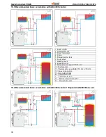
Page 34: ... Domestic water tank 6 4 way valve 7 Heating circuit 8 Expansion tank 9 Drain valve Honeywell TS 131 10 Discharge fan 11 Thermostatic valve ESBE VTC 312 VTC 512 12 3 way mixing valve 13 Accumulation tank M Servo motor unit T Thermometer KTY TE External thermometer KTY TP Pump thermostat 16 4 Recommended basic schematics with AK 4000 control Expander AK4000 Basic set ...

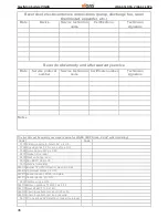
Page 35: ...re Sensor connection modul Cable set for STB fuse Fan cable Power cord EU Servounit Belimo 24V Pellet EXPANDER AK4000EP Motor gear box TTM 203 Ignition coil Room thermostat Memory modul AK4000M Expander AK4000 Discharge fan Container sensor type KTY Motor sensor type KTY Ultrasound transmitter Ultrasound receiver Gas sensor type PT 1000 Boiler sensor UNI type KTY STB fuse 100 C Capacitor Fan EBM 1...

Page 36: ...use Code when ordering Code Code 0102 Ceramic nozzle 3 hole LAC pic 3 9 0104 Fire clay brick P4 for iron ash pic 3 12 3008 Servo Belimo 24V pic 3 39 0401 Gasket Door seal 0405 Heat exchanger seal 0516 Fan EBM 108 pic 3 7 0601 Handle complete 0633 A Burner 18 DPA refractory steel pic 3 24 0634 A Tourniquet blades pic 3 33 0636 C Feeder device 18DPA complete 0637 A Feeder device pic 3 32 0638 Igniti...

Page 37: ... 2012 EN 61010 1 A2 2000 EN 50081 1 1995 EN 50082 1 2002 EN 61000 3 3 2000 EN 61000 3 2 2000 A1 A2 2001 Date of production control Date of purchase Date of commission Stamp and signature of seller Stamp and signature of producer VIGAS DPA kW Product VIGAS DPA kW Serial number User name and address Date of purchase Date of commission Signature of authorized technician Stamp and signature of seller ...

Page 38: ...nths from the date of purchase Warranty is valid only if the boiler is commisioned by an authorised technician Warranty is valid only if the electric equipment is added according to regulation by authorized technician and recorded in relevant documents of connected devices Warranty applies only to the boiler construction used material and complete boiler unit Warranty does not apply Consumer mater...

Page 39: ... at minimum output elmin kW 0 014 0 010 Own electricity consumption in standby mode PSB kW 0 001 0 001 Own electricity consuption in firing mode Pzap kW 1 773 1 693 Sezonne emissions heating area TČ1 PM mg m3 13 2 21 0 Sezonne emissions heating area POZ1 OGC mg m3 14 4 19 7 Sezonne emissions heating area CO1 CO mg m3 260 9 360 5 Sezonne emissions heating area NOx1 NOx mg m3 156 1 139 3 Characteris...

Page 40: ...LOVAKIA Production plant Pavel Vigaš VIMAR Príboj 796 976 13 Slovenská Ľupča SLOVAKIA tel 00421 48 4187 022 fax 00421 48 4187 159 WWW VIMAR SK WWW VIGAS EU vimar vimar sk Serial number All technical changes are reserved by Pavel Vigaš VIMAR 2017 Displey ver 2 00 Pictures are illustrative and may differ from reality 26 4 2017 10 27 40 ...

Reviews: