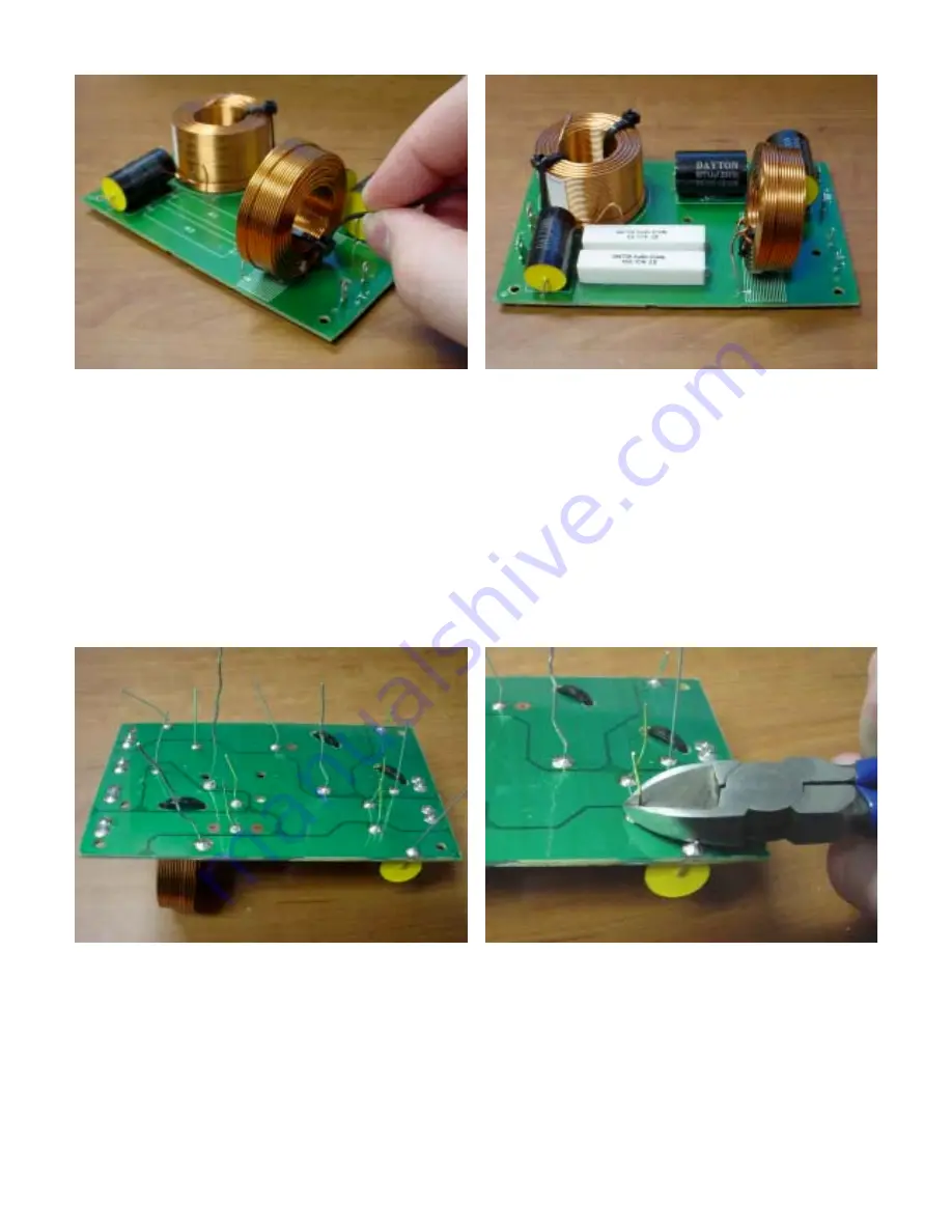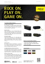
7
Wire tie inductors in place for additional security
Completed component installation with glue and
wire ties
Once all of the components have been secured and have their leads going through the board, we can flip it over
and make the solder connections. On the inductors, make sure that the “silver” tinned section of the lead is what
you are soldering to. Attempting to solder to the copper-colored or red insulated portion of the inductor lead will
result in a failed connection.
To solder effectively, place the soldering iron tip so that it is touching both the component lead and the PC board.
This will allow both portions to heat simultaneously, and will ensure a good flow of solder between the two. After
heating the board and leads for several seconds, add solder to the joint to form an effective connection. A good
solder joint will have a conical shape, and will not look “blobby” or “spherical.”
After all connections are made, the remaining component leads on the rear of the board can be trimmed down
with a pair of side cutters or other electrical cutters.
Rear view of all connections
Trim component leads with cutters
We can now add the connecting wires for the inputs and drivers. Connect the input, output, and tweeter wires to
the respective terminals on the PC board. The wire with the .25" terminals is the input wire. The longer wires will
be for the tweeters and the shorter wires will be for the woofers. Make sure that the positive terminals are
connected to the positive (red) wires in all locations.


