6
5. Crossover Assembly Instructions
For the system to perform properly, it is important that the crossover be assembled correctly. Incorrect assembly
can cause damage to the speaker drivers or your amplifier, so please take time to work carefully and to check
your work as you go.
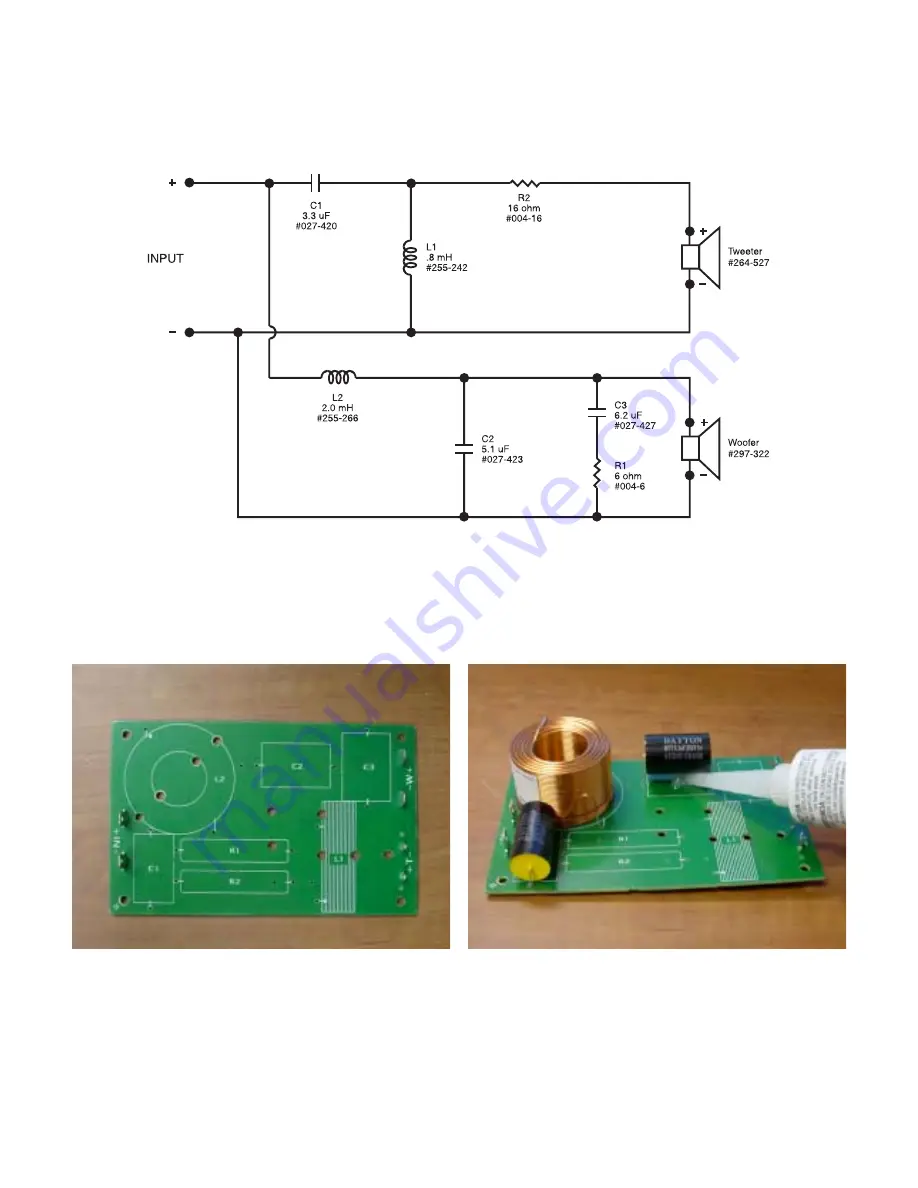
The crossover boards have a printed pictorial layout on them that includes an outline of the component and a
part label. Please refer to the parts list and schematic for a list of which components go in each location. Match
the component label from the description on the parts list to the label on the PC board.
Note:
The following photographs are of a “generic” crossover assembly and will not exactly match the look of
your particular system
Component locations on PC board with labels
Insert components into PC board, securing
with silicone or hot melt glue
Each component will have two leads that correspond to holes on the PC boards. Put the components into place
with the leads going through their appropriate holes, following the pictorial on the board. Directionality on the
components is not important; either end of each component can go into either hole. It is recommended that each
component be secured to the board with hot-melt or silicone to prevent any possible vibration of components.
Cable ties are recommended on the inductors to hold them in place more firmly, especially if you are using
silicone.


