background image

38

8.7 DELETING IMAGES & VIDEOS

8.7.1 DELETING INDIVIDUAL IMAGES/VIDEOS

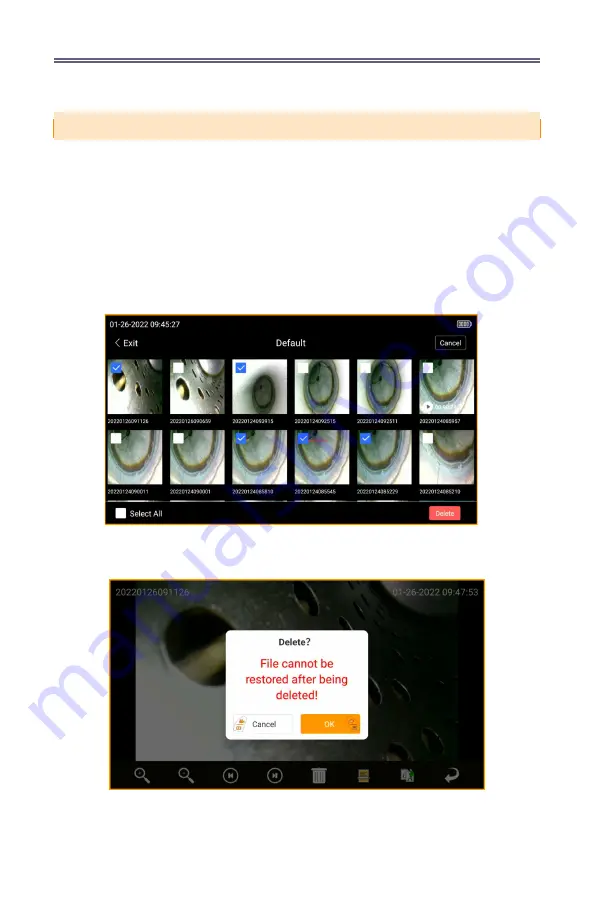
While in the Folder Management setting, by touching any folder and then selecting 

the Edit icon at the top right corner, a user is able to multi-select images and videos for 

deletion. After the selection is complete, touch Delete to remove the selected images and 

videos. A prompt will be displayed noting “File cannot be restored after being deleted!”. 

Select Ok to confirm or Cancel to exit.
While in Image Browsing mode, by touching the Delete icon, a user can delete an  

individual image or video. A prompt will be displayed noting “File cannot be restored after 

being deleted!”. Select Ok to confirm or Cancel to exit. 

Fig. 8-9 

Selecting and deleting individual images and videos while 

in the Folder Management setting

Fig. 8-10 

Selecting and deleting individual images and videos 

while in the Image Browsing mode with the Delete Icon

Summary of Contents for VJ-4

Page 1: ...MECHANICAL ARTICULATING VIDEO BORESCOPE USER MANUAL VJ 4 2 2mm 2 8mm ...

Page 2: ...ions 14 7 2 Button Functions 15 7 3 Overview of Menu Functions 16 Menu Mode Functions 16 LED Brightness 18 Screen Brightness 18 Display Ratio 19 Target Distance 19 Grid Measurement 20 Image Browsing 21 Zoom Function 21 Image Rotation Mirror 21 Negative Color 22 Image Freeze 22 White Balance 22 7 4 System Settings Menu 23 Language 24 Date Time 24 Video Format 24 Image Format 24 Folders 25 SD Card M...

Page 3: ... Deleting Images Videos 38 Deleting Individual Images Videos 38 Deleting All Images Videos 39 8 8 System Settings Image Review and Editing 40 Image Review Icons 40 Image Editing Icons 41 Editing Saved Images 42 Draw Icon 42 Arrow Icon 43 Text Icon 43 Reference Measurement 44 Settings Icon 48 IX STORAGE AND MAINTENANCE 49 9 1 Cleaning 49 Cleaning The Insertion Tube 49 Cleaning the OLED Touch Screen...

Page 4: ...2 ...

Page 5: ...Too much force or using an object besides the provided stylus or fingertip could damage the screen DO NOT over torque crease twist or fold the insertion tube Doing so could damage the articulation control wire assemblies and or electrical wiring ONLY USE the power adapter provided by ViewTech DO NOT yank or attempt to forcefully remove the insertion tube if it becomes stuck inside the equipment be...

Page 6: ...splay DO NOT cover the unit with a plastic bag or other similar protective covering during use It may cause the unit to overheat and damage the internal circuitry DO NOT use or store the borescope in a high temperature high humidity or high radiation environment BATTERIES BATTERY CHARGING Follow the instructions below for battery care and proper charging to prevent leakage overheating smoke explos...

Page 7: ...ge the batteries before use and after extended use 6 Remove the batteries from the borescope if the scope will not be used for more than 30 days otherwise it may cause damage to the borescope fire or personal injury REMINDER 1 These are high output batteries Please use the batteries properly or it may cause damage from leakage or excessive heat Always check the orientation polarity and load batter...

Page 8: ...lay Monitor Articulation Control Brightness Control Control Buttons Playback Audio Microphone Internal storage Data I O ports Batteries Operating Method Dimensions Weight Menu Functions and Options User Interface File Management Image Control Image Format Video Format Language Operating Limits Run Time Operating Temp Base Unit Operating Temp Insertion Tube IP Rating Insertion Tube II PRODUCT SPECI...

Page 9: ...ED brightness adjustment Two multi function mini joysticks and left right buttons Photos videos w wo audio thumbnail view 3 5mm port 32 GB SD Card 10 000 photos 8 hours video SD card HDMI USB Type C Two 18650B PCB Protected Li ion batteries rechargeable One handed portable 13 6 x 6 2 x 7 3 2 09 lbs 95 kg Pop up menu operation menu navigation touchscreen Photo and video recording playback thumbnail...

Page 10: ...2 18650B Li ion batteries 2 plus spares 3 18650B Li ion battery charger 4 USB cable 5 Micro USB C cable 6 HDMI cable 7 AC DC power adapter 8 32GB SD card card case 9 User manual 10 Stylus pen 11 Shoulder strap Fig 3 1 VJ 4 and Case With All Contents ...

Page 11: ...e great effort and expense to access directly The VJ 4 video borescope consists of an insertion tube with distally mounted camera LEDs and base unit with control panel OLED display monitor power source and all necessary circuitry The VJ 4 is available in a variety of configurations suitable for different tasks with insertion tubes of various lengths and diameters as well as different light wavelen...

Page 12: ...5 Right Control Button 6 Left Mini Joystick 7 Articulation Control Joystick 8 Right Mini Joystick 9 UV Light Flashlight 10 White Light Flashlight 11 Photo Capture Trigger 12 Camera LED Module 13 Insertion Tube 14 USB C Port 15 HDMI Video Output Port 16 Headset Mic Jack Port 17 SD Card Port 18 Battery Compartment Fig 5 1 Part names and functions ...

Page 13: ...it gently After the insertion tube is removed use your other hand to grip and remove the base unit 6 2 POWER SUPPLY PREPARATIONS REMOVING THE BATTERY COMPARTMENT Using your thumb and forefinger press the two buttons on the sides of the battery chamber at the base of the handle and gently remove the battery compartment from the handle Fig 6 2 Fig 6 1 The VJ 4 case Fig 6 2 Removing the battery compa...

Page 14: ... required When batteries no longer hold a charge replace batteries with new 18650B Li ion batteries with PCB protection circuit WARNING The batteries cannot be charged while still in the borescope Use only the supplied AC power adapter for recharging the battery input of 100 240 V 50 60 Hz AC The adapter output voltage is 12V with an electric current of 3A Use of an adapter that does not comply wi...

Page 15: ...rging is finished when the charger shows 100 for each battery ATTENTION Ensure the batteries are correctly loaded into the charger The charger has built in circuitry to prevent over charging however the batteries should be removed from the charger and placed back into the carrying case or the borescope after they are fully charged Fig 6 5 Battery charger Fig 6 4 Battery compartment ...

Page 16: ...S 7 1 BUTTON POSITIONS Fig 7 1 Button Diagram front view Fig 7 2 Button Diagram side view 1 Left Control Button 2 Right Control Button 3 Left Mini Joystick 4 Right Mini Joystick 5 Photo Capture Trigger 6 Articulation Control Joystick ...

Page 17: ... Also used to navigate through menu or system settings mode Right Control Button Short Press switch between live image mode and menu navigation mode Long Press enter the system settings mode Select OK in system settings mode Right Mini Joystick Move Up Down image zoom in out Move Left Right image flip mirror Press down on the center to switch to default setting or confirm a selection Photo Capture...

Page 18: ... control buttons or the touchscreen The two mini joysticks consist of a Left Mini Joystick LMJ and a Right Mini Joystick RMJ The two control buttons are a Left Control Button LCB and a Right Control Button RCB The overarching framework of this UI consists of three icon screens which present three different levels of the user interface Live Image Mode Menu Navigation Mode System Settings Mode Fig 7...

Page 19: ...ty see Hide Icons Delay P 27 To adjust LED Brightness Move the LMJ up or down Image Zoom Move the RMJ up or down Display Brightness Move the LMJ left or right Image Rotation Move the RMJ left or right The Menu Navigation Mode consists of the four icons of the Live Image Mode plus eight additional icons that control Display Ratio Negative Color Target Distance Image Freeze Grid Measurement White Ba...

Page 20: ...ive Image Mode top 4 icons and Menu Navigation Mode all 12 icons LED Brightness Zoom Function Screen Brightness Image Rotate and Mirror Display Ratio Negative Color Target Distance Image Freeze Grid Measurement White Balance Image Browsing System Settings LED BRIGHTNESS The LED brightness level ranges from 1 10 SCREEN BRIGHTNESS The screen brightness level ranges from 1 10 ...

Page 21: ...tions Far Range Mode used for long distance inspections User Defined users define and set the camera settings When User Defined Distance Mode is selected the user can manually change color and exposure settings in two tabs In the Camera Color setting tab the user can adjust Brightness Contrast Hue Saturation Sharpness Gamma and Gain In the Exposure Control setting tab the user can adjust the Expos...

Page 22: ... menu option allows three different size grid sizes to be displayed on the screen to assist with estimating the dimensions of a specific object on the screen No grid selection 20mm grid 10mm grid 5mm grid Fig 7 9 User Defined Exposure Control Settings ...

Page 23: ...n page 25 ZOOM FUNCTION There are 10 different zoom ratios to choose from 1 15 1 30 1 45 1 60 1 75 1 90 2 05 2 20 2 35 and 2 50 IMAGE ROTATION MIRROR The live image can be rotated and mirrored with several options available This is the actual image and default setting This is 180 degree rotation of the actual image This is left and right mirroring of the actual image This is up and down mirroring ...

Page 24: ...e freeze REMINDER The frozen image may be blurry if it was captured while the camera insertion tube was in motion WHITE BALANCE This menu option allows for automatic white balance or manual white balance The automatic white balance automatically detects the color temperature of the photographed object and makes color adjustments To set the manual white balance at the site of use take a white piece...

Page 25: ...n touch the icon or press down with the mini joystick to select The System Settings Menu controls operational settings for the borescope in the following categories Language Date Time Video Format Image Format Folders SD Card Management Update Software Hide Icons Delay Annotation Review Settings and Auto Shut Down Settings on the first screen The second page of settings includes WiFi Setting Camer...

Page 26: ...rmat VIDEO FORMAT Two options for video format are available AVI or MP4 IMAGE FORMAT Three options for image format are available JPG PNG or BMP Note BMP is the largest size and JPG is the smallest size Fig 7 17 Image file formats available Fig 7 14 Languages available Fig 7 15 Date and time selection screen Fig 7 16 Video file formats available ...

Page 27: ...signating a default folder To add a new folder first select Create New Folder Next the new folder will need to be named After naming the folder select OK to save By selecting Folder options available include Rename Delete or Make Active Folder Fig 7 18 Main folder screen Fig 7 19 Prompt to add and name a new folder Fig 7 20 Folder management options ...

Page 28: ...7 23 Prompt displayed when deleting a folder By selecting Rename the name of the folder can be edited or changed To delete a folder select delete Note Folders and images videos within the folder are not able to be restored after being deleted By selecting Make Active Folder this folder becomes the destination folder for future images and videos ...

Page 29: ...g a live image the icons in the Menu Navigation mode will automatically turn off after a set period of time of non use The hide icons delay will change the time it takes for the screen to switch from Menu Navigation Mode all icons displayed on the main screen to Live Image Mode only four icons displayed on the menu screen Fig 7 24 Prompt displayed when selecting to reformat the SD card Fig 7 25 Pr...

Page 30: ...y return to the live image mode Video Annotation Selecting yes will cause a dialog box will appear before a video is recorded asking whether or not annotation should be added to the video This annotation will appear during the recording and playback Fig 7 28 Annotation selection settings NOTE If video annotation is set to No and image annotation is set to Yes images captured while recording a vide...

Page 31: ...tation Fig 7 32 Select previously saved annotations To create a new annotation select the plus icon A keyboard will appear where the text can be added After typing the annotation desired touch OK or press the Right Control Button to save Use the drop down arrow to select a previously saved annotation ...

Page 32: ...ete all previously saved annotations with select all If previously save annotations need to be deleted select the delete icon The user is able to select one or select all annotations Once all items that need to be deleted are selected touch delete or press the Right Control Button to have them removed Tapping the settings icon will allow you to change the font size and color that is displayed with...

Page 33: ...he WiFi setting enables the VJ 4 to be wirelessly connected to a WiFi enabled device such as a smartphone tablet or computer A WiFi streaming app must be loaded onto the device in order to display the image from the borescope Visit www ViewTech com wifi for a list of suggested screensharing smartphone apps along with FAQs Fig 7 37 Auto Shut Down selection options Fig 7 38 WiFi Setting selection ...

Page 34: ...tip and can be displayed on the live inspection screen when set to On NOTE This reading is accurate within 10ºF 5ºC If this level of accuracy is not helpful or the display is distracting it is recommended that this feature be turned off Fig 7 40 Estimated Temperature Displayed Fig 7 39 Camera Temperature Options ...

Page 35: ... is connected to a computer If inactive is selected image and video files will not be displayed when connected to a computer NOTE powering off the borescope will return USB mode to the default setting of Read SD Card Files ABOUT The About setting will display the current software version Fig 7 41 USB Mode Setting Options Fig 7 42 About setting display ...

Page 36: ... debris Clean as necessary using the cleaning swabs provided being careful not to flex the bending section while doing so 8 2 TURNING ON OFF Press the on off button see Fig 8 2 near the top corner of the base unit The borescope will power up and the LCD will display the real time image captured by the camera LED module Fig 8 1 Cleaning the camera at the end of the insertion tube Fig 8 2 On Off but...

Page 37: ...aight before starting the inspection DO NOT attempt to articulate the bending section with the joystick while the insertion tube is coiled as this will result in breakage of the articula tion control wires After the insertion tube enters the inspection port adjust the brightness as necessary and use the LCD monitor to see the internal view Manipulate the joystick as needed in order to steer the in...

Page 38: ... equipment being inspected If the insertion tube becomes stuck during the extraction gently rotate the joystick until it becomes dislodged and then pull the insertion tube out Never yank or forcefully remove the insertion tube 8 5 RECORDING IMAGES Still images and video can be captured and recorded during live viewing mode and are stored on the SD card 8 5 1 LOADING THE SD CARD Open the rubber cov...

Page 39: ...ideos currently saved in the default folder 2 To view all folders along with the images and videos saved within the folders select the Image Browsing icon in the Menu Navigation screen 8 6 1 MULTI IMAGE VIEW By selecting the Image Browsing icon and selecting a folder all videos and images within that folder will be displayed as thumbnails Use the Right Mini Joystick or touchscreen to scroll betwee...

Page 40: ...pt will be displayed noting File cannot be restored after being deleted Select Ok to confirm or Cancel to exit While in Image Browsing mode by touching the Delete icon a user can delete an individual image or video A prompt will be displayed noting File cannot be restored after being deleted Select Ok to confirm or Cancel to exit Fig 8 9 Selecting and deleting individual images and videos while in...

Page 41: ...te to remove all images and videos A prompt will be displayed noting File cannot be restored after being deleted Select OK to confirm or Cancel to exit REMINDER All Images and Video can be viewed organized renamed and deleted by removing the SD card 8 5 1 from the VJ 4 Borescope and using the supplied SD card reader with your computer Fig 8 11 Selecting and deleting individual images and videos wh...

Page 42: ...om Out Zoom out on photos Previous Image Move to the previous image Next Image Move to the next image Delete Image Delete the current image Enter Image Editing Mode Enter editing mode Rename The Current Image To rename an image or video file name Return To Previous Screen Go back to previous screen ...

Page 43: ...Select to type text on an image Reference Measurement Used in reference measurements Save Image Save image with changes that have been made Settings Icon Change the font size line size font color curve color or arrow color Undo Changes Revert to original image prior to any changes being made Return To Previous Screen Go back to previous screen ...

Page 44: ... When viewing a saved image by selecting the Enter Image Editing Mode icon users are able to view all image editing options Once in Image Editing Mode the Draw icon allows users to draw or write free hand on an image with the stylus or finger Fig 8 14 The Draw Icon ...

Page 45: ... 16 The Text Icon and Keyboard When the Text icon is selected first touch the screen to locate the placement of the annotation Next type the text to be displayed and touch OK Fig 8 15 The Arrow Icon The Arrow icon is used to add arrows to an image ...

Page 46: ... to Calculate Reference Measurement After selecting an image to use in Reference Measurement mode begin by tapping two points from left to right on the screen to indicate your measure ment reference Be sure to tap the Save icon in order to save all changes that have been made to the image ...

Page 47: ...nce Measurement After completing the reference line a red line and the distance pixel value will appear Next tap two points to indicate the distance you would like to be measured A green line and its pixel value will appear Fig 8 20 The Green Line is the Length to be Measured ...

Page 48: ...er both a red reference line and green line to estimate measurement are completed input a number for the known length of the reference This is the actual length of the red reference line and can be measured in millimeters centimeters or meters Once the length of the reference line has been input the measured lengths will be displayed ...

Page 49: ...mate additional lengths to be measured based on the original length of reference by tapping new areas to be measured New green lines will appear showing the new measurements Lastly be sure to save the image for measurement results to be saved If you were to exit the image without saving all measurement information will be removed ...

Page 50: ...en is where font size line size font color line color and arrow color can be adjusted Fig 8 25 The Settings Icon Screen Fig 8 26 Rename Current Image Icon After editing saved images it is generally helpful to rename any image that would need to be referenced later ...

Page 51: ...BASE UNIT Wipe the base unit with a dust free cloth as needed 9 2 REPACKING 1 Return the borescope to the case carefully in order to avoid unintentional damage to the insertion tube or camera LED module 2 Be sure that the joystick is in the center neutral position and that the bending section is straight prior to inserting the borescope into the case 3 When returning the borescope to the case firs...

Page 52: ...Stop using allow unit to cool down and then restart Triggered by too low battery level Charge the battery Unclear image The camera lens or LCD monitor is dirty Wipe clean with a dust free cloth or swabs Joystick resistance feels high A lot of pressure is required to move the joystick The insertion tube is coiled or bent too much Straighten the insertion tube as much as possible 10 2 REPAIR Please ...

Page 53: ...s opened customized or tampered with by an unauthorized techni cian If any repair or modification is performed by an unauthorized technician ViewTech Borescopes will not be responsible or liable for any damage to persons or property that may result REPAIR PROCEDURE To initiate a repair regardless of whether the repair is under warranty or not an RMA Return Merchandise Authorization number must be ...

Page 54: ...52 CERTIFICATION Low voltage directive and EMC directive Conforms to CE WEEE directive Conforms to WEEE RoHS directive Conforms to RoHS ...

Page 55: ...53 NOTES ...

Page 56: ...54 NOTES ...

Page 57: ...55 NOTES ...

Page 58: ...56 NOTES ...

Page 59: ...Traverse City Michigan USA 1 231 943 1171 WWW VIEWTECH COM 07 22 SCAN THE QR CODE BELOW TO VIEW THE MOST RECENT VERSION OF THE VJ 4 USER MANUAL IN A DIGITAL FORMAT ...

Reviews: