background image

Getting Started

3

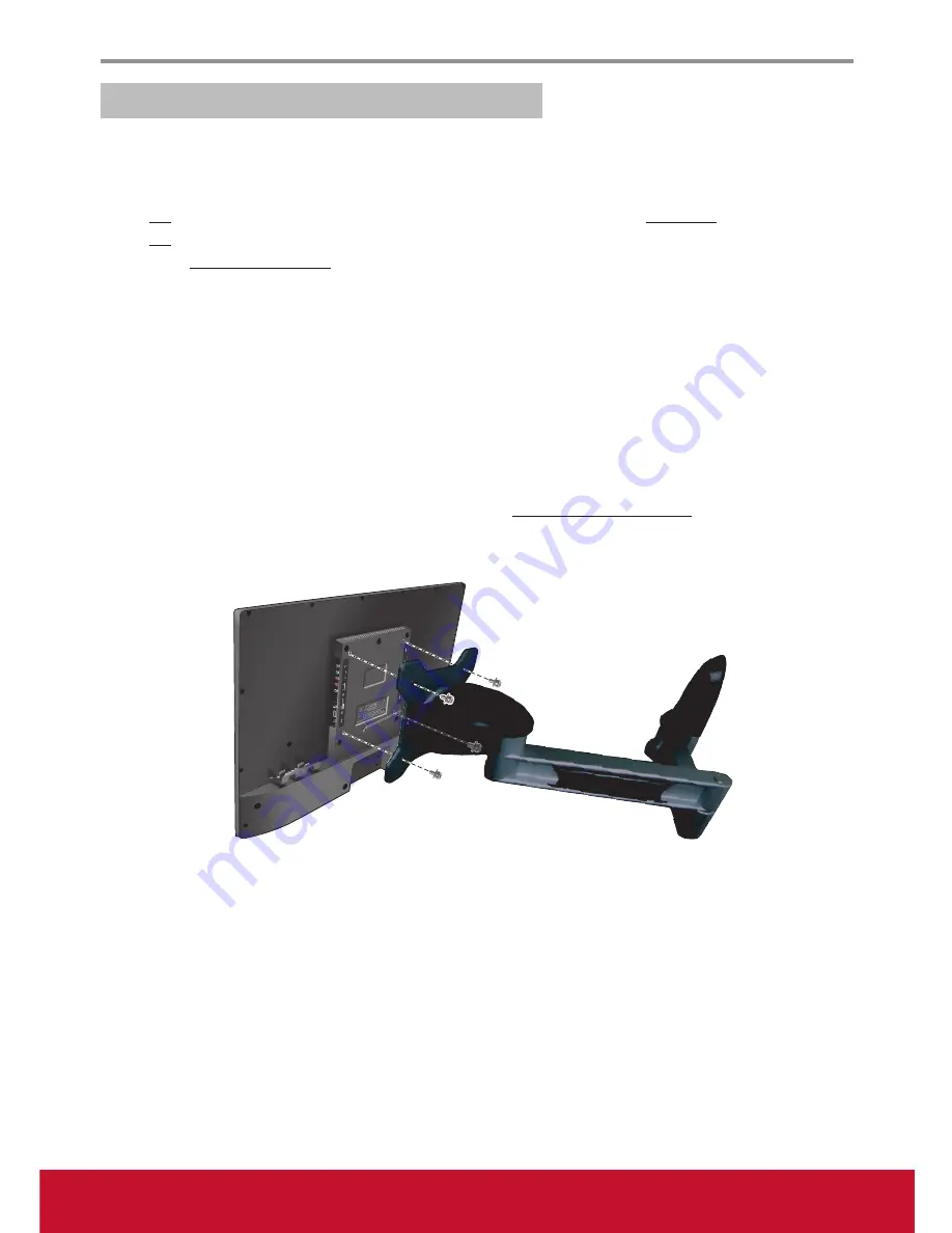
Mounting ViewSonic LCD TV to the wall

The LCD TV can be used in a free standing position or wall-mounted. Before installing the product to the 

wall, please consider the following guidelines:

Read the Important Safety Instructions, at the start of this manual. 

• 

Do 

• 

not install in a moist or wet environment. This equipment is intended for indoor use.

Do 

• 

not

 install near heat source, or strong magnetic fields.

Use only 

• 

ViewSonic approved wall-mounting brackets to support the LCD TV weight.

Before attaching the wall mount plate to the back cover, ensure the product is working.

• 

If your LCD TV is already set up for free-standing operation, you need to first remove the stand before 

• 

mounting the device to the wall.

To attach the wall-mount bracket to LCD TV safely, please use the following guidelines:

Disconnect the power and any other cables that might hinder moving the LCD TV. 

• 

Set the LCD TV on a table or work surface, placing the screen face down on a towel or woolen blanket to 

• 

protect the screen surface from damage while installing plate.
Before installing the LCD TV on the wall, ensure you have recorded the product serial number on page (i) 

• 

of the User Guide, as you will need the serial number to request service should there be a service need.
Install the wall mount plate to the LCD TV using screws 

• 

NO LONGER than 12mm, as longer screws 

found in universal (non-ViewSonic) wall mount kits may damage the power supply causing the unit to fail. 

The wall-mount screw type is M6 x L12.

Mount the wall mount bracket to the wall ensuring use of proper screws to support the installation. Ensure 

• 

there is at least 3cm of space surrounding any air-vents of your LCD TV to allow adequate cooling during 

operation.
Hang the LCD TV wall mount plate to the wall mount bracket, completing installation.  

• 

Enjoy your ViewSonic LCD TV!

Summary of Contents for VS14652-1M

Page 1: ...in a safe manner as well as registering your product for future service Warranty information contained in this User Guide will describe your limited coverage from ViewSonic Corporation which is also...

Page 2: ...cifications VESA 4 Front View of the Product 5 Rear View of the Product 6 Connecting the LCD TV 7 Cable System or VHF UHF Antenna System 7 Cable System and VHF UHF Antenna System 7 HD Cable Box HD Sat...

Page 3: ...adio TV technician for help Warning You are cautioned that changes or modifications not expressly approved by the party responsible for compliance could void your authority to operate the equipment Fo...

Page 4: ...ed biphenyls PBB 0 1 0 1 Polybrominated diphenyl ethers PBDE 0 1 0 1 Certain components of products as stated above are exempted under the Annex of the RoHS Directives as noted below Examples of exemp...

Page 5: ...this document may change without notice No part of this document may be copied reproduced or transmitted by any means for any purpose without prior written permission from ViewSonic Corporation Produ...

Page 6: ...uch as power supply cord or plug is damaged liquid has been spilled or objects have fallen into the apparatus the apparatus has been exposed to rain or moisture or the unit does not operate normally o...

Page 7: ...BLY FATAL Be sure the antenna system is grounded so that it can provide some protection against voltage surges and built up static charges Section 810 of the National Electrical Code NEC in the U S A...

Page 8: ...fire or an electric shock Do not place any objects on the TV MOISTURE Moisture and flammable objects Keep the product away from moisture Do not expose this appliance to rain or moisture Do not place o...

Page 9: ...D screen surface to direct sunlight It is likely to damage the LCD panel Do not push or scratch the LCD screen or place objects on top of the TV The image may be uneven or the LCD panel may be damaged...

Page 10: ...ler LCD TV Remote Control with batteries Stand screws ViewSonic User Guide ViewSonic Quick Start Guide Power adapter Getting Started SOURCE FAV EXIT MUTE MENU POWER RETURN 1 2 3 4 5 6 7 8 9 1 ENTER CH...

Page 11: ...he foot stand and secure it with the included screws Please fasten with a cross screw driver see Figure 2 3 Stand the TV up see Figure 3 Disconnecting the Stand 1 Carefully place the TV screen side do...

Page 12: ...onnect the power and any other cables that might hinder moving the LCD TV Set the LCD TV on a table or work surface placing the screen face down on a towel or woolen blanket to protect the screen surf...

Page 13: ...ides the standard dimensions for wall mount kits as shown in the table above To find the perfect mount please browse www viewsonic com or call our service team United States 1 800 688 6688 Canada 1 86...

Page 14: ...on the OSD menu 4 Channel Select CH q Decrease the channel number Move upward to the next item on the OSD menu CH p Increase the channel number Move upward to the previous item on the OSD menu 5 Inpu...

Page 15: ...ll be muted 4 SPDIF Optical output Connect to the SPDIF input of A V device 5 Remote Control output Connect to an IR emitter This will enable the remote control of external equipment 6 USB Connect to...

Page 16: ...d antenna programming as shown below Remember to set the TV CATV setting in the TV menu to Air or Cable for the type you choose HD Cable Box HD Satellite Box You can also enjoy high definition program...

Page 17: ...1024x768 V V SXGA60 1280x1024 V V WXGA60 1360x768 V V 1280 x 800 V V 480i60 V NA 576i50 V NA 480P60 V NA 576P50 V NA 720P50 V NA 720P60 V NA 1080I50 V NA 1080I60 V NA 1080P50 V NA 1080P60 V NA 1080P2...

Page 18: ...le Rear side of the TV Component cable CATV Satellite antenna cable Audio cable HD cable box HD satellite box COMPONENT VIDEO OUT Pr Y VIDEO DVI HDTV OUT HDMI OUT OUT IN AUDIO L R Pb LINE OUT AV cable...

Page 19: ...onnect the PC IN jack to the PC using a 15 pin cable and audio cable PC Timing Reference Chart Mode Resolution H sync kHz V sync Hz Pixel clock MHz Polarity Support IBM VGA 720 x 400 31 47 70 09 28 32...

Page 20: ...rsonal injury Dispose of the battery in accordance with local laws and regulations Keep the batteries away from children or pets When the remote control will not to be used for an extended period remo...

Page 21: ...uide EPG It contains the program information for the channel you re watching 7 MTS Press this button to choose the available sound output that is preset by TV broadcasting station Available options Mo...

Page 22: ...splay menu on 15 C C Press to select the Closed Caption menu in the TV or AV mode 16 CH Press to change the channels up or down 17 INFO Press to display the current state of the TV 18 SLEEP Press repe...

Page 23: ...le 4 Press or to select Auto Channel Search then press ENTER to enter to perform channel scan 5 The channel scan may take a while to complete and after it is done the screen will return to the first f...

Page 24: ...sting the Volume Press VOL to adjust volume To turn off the volume press MUTE To restore volume press MUTE again or press VOL directly Viewing the Displayed Information To display the current informat...

Page 25: ...5 Press or to highlight Favorite check box and press ENTER to confirm your selection A icon indicates the selected channel has been added into the Favorite List 6 To cancel the selection press ENTER a...

Page 26: ...press ENTER to enter the menu 3 Press or to select Channel Settings then press to enter Channel Settings submenu 4 Press or to select the channel you want to customize its label 5 Press or to highligh...

Page 27: ...ess or to select your desired MPAA ratings level The MPAA ratings level are defined as following G general audience PG parental guidance suggested PG 13 recommended for children 14 years of ageor olde...

Page 28: ...ing the Canada Ratings system 1 Press MENU to display the OSD main menu 2 Press or to select PARENTAL menu then press ENTER to enter the menu 3 Enter the password 4 Press or to select V CHIP then pres...

Page 29: ...to select your desired Canadian French rating level The Canadian French rating levels are defined as following G general 8 ans children eight years and older 13 ans not appropriate for children of les...

Page 30: ...ENTAL menu then press ENTER to enter the menu 3 Enter the password 4 Press or to select Change Password then press to enter its submenu 5 Enter the old password on Old PIN 6 Enter your new password on...

Page 31: ...e default settings TV ID Setting To set ID number to TV for RS232 function 1 Press MENU to display the OSD main menu 2 Press or to select OTHERS menu then press ENTER to enter the menu 3 Press or to s...

Page 32: ...ress or to select PC Settings then press ENTER to enter its submenu 6 Press or to select Auto Adjust Horizontal Position Vertical Position Clock or Phase and press or to adjust the setting 7 Press EXI...

Page 33: ...ector on the rear side of the TV 2 Press SOURCE to display the Source Select menu 3 Press or to select USB then press ENTER to confirm the setting The USB menu appears on the screen 4 Press or to sele...

Page 34: ...tion Slideshow Interval Set the interval time between each slide displays 3 S 5 S 10 S 30 S 1 Min 30 Min Slideshow Effect Select the transition effect between each slide displays Random Off Wipe Right...

Page 35: ...ness of the edges of elements in the picture Screen Size Select the aspect ratio of the display Zoom Normal Wide Cinema PC Settings only available on VGA source Adjust the PC display settings Auto Adj...

Page 36: ...dio mode Only available for digital channels Digital Audio Output Select the type of digital audio output to an external audio system Off PCM Raw Equalizer Settings Apply a preset equalizer setting Of...

Page 37: ...k UnRated Show Block all unrated programs Downloadable Rating Download updated rating data Clear Downloaded Data Delete the downloaded rating data Downloadable Rating and Clear Downloaded Data options...

Page 38: ...t the time automatically from a digital channel signal Setup Time Set the current date and time Day of Week Display the day of the week Daylight Saving Time Set to turn on off daylight saving Time For...

Page 39: ...the TV to automatically turn off if it is left idle for 10 minutes Usage Monitor Select to calculate the overall monitor usage Audio Only Output audio from the TV speakers but turn off the TV display...

Page 40: ...another channel The Cable TV signal may be scrambled or encoded Please contact your local cable operator Make sure that the cable connection to other components are properly installed Make sure that s...

Page 41: ...eration In this case operate the unit after first turning on the power of the TV and the AVC System or unplug the AC cord for 1 to 2 minutes then replug again Power is cut off suddenly Make sure the s...

Page 42: ...ax Audio Output 1 Earphone jack 1 SPDIF optical RS232 Output RS232 communication IR control Output IR pass through signal NEC 38KHz RC5 38KHz Power Voltage AC 100 240V 50 60Hz Operating conditions Tem...

Page 43: ...n the rear side 1 Connector type DSUB 9 Pin Male 2 Pin Assignment 2 2 Communication Setting Baud Rate Select 9600bps fixed Data bits 8bits fixed Parity None fixed Stop Bits 1 fixed 2 3 Command Message...

Page 44: ...command Reply 0x2Dh Invalid command Reply Command Function command code One byte ASCII code Value 1 3 Three bytes ASCII that defines the value CR 0x0D Set Function format Send Command Type s Name Len...

Page 45: ...elect 8 s 22 000 TV 001 AV 002 S Video 003 YPbPr 004 HDMI 014 HDMI2 024 HDMI3 005 DVI 006 PC VGA 1 No need for USB 2 For the case of two more same sources the 2nd digital is used to indicate the exten...

Page 46: ...DTV This is the power up default on the HDTV Pass through RCU has no effect on HDTV and all RCU command codes are transmitted to FC via the RS232 port Setup wizard 8 s C 43 000 Disable 001 Enable Disa...

Page 47: ...information The Get Function packet format consists of 9 bytes which is similar to the Set Function packet structure Note that the Value byte is always 00 Get Function description Length Total Byte o...

Page 48: ...8 0x30 0x35 0x72 0x62 0x30 0x36 0x37 0x0D Example2 Get Brightness from TV 05 but the Brightness command ID is error and it is NOT in the command table Send Hex Format Name Length ID Command Type Comma...

Page 49: ...PC sets the TV monitor to Remote Control Pass through mode the TV shall send a 7 bytes packet followed by CR in response to RCU button activation Note that in this mode the RCU shall have no effect o...

Page 50: ...OK ENTER 1F EXIT 20 21 22 23 24 25 26 27 28 29 2A 2B 2C 2D 2E 2F NOTE 1 This IR pass through code is different with RCU key code 2 Special control sequence for POWER key under IR pass through mode 2 1...

Page 51: ...om Canada www viewsonic com T Toll Free 1 866 463 4775 T Toll 1 424 233 2533 F 1 909 468 3757 service ca viewsonic com Latin America Argentina www viewsonic com la T 0800 4441185 soporte viewsonic com...

Page 52: ...about receiving service under warranty contact ViewSonic Customer Support please refer to Customer Support page You will need to provide your product s serial number 2 To obtain warranted service you...

Page 53: ...on in the space provided below on your purchase for your future use Please retain your receipt of proof of purchase to support your warranty claim For Your Records Product Name _______________________...

Page 54: ...777 3124014 E Mail aquevedo compusupportcva com Distrito Federal QPLUS S A de C V Av Coyoac n 931 Col Del Valle 03100 M xico D F Tel 01 52 55 50 00 27 35 E Mail gacosta qplus com mx Guadalajara Jal SE...

Page 55: ......

Reviews: