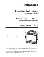
background image

100pF on pin-196

E

GM5120

3

6

Thu rsday, July 10, 2003

Gensis Chip (Scaler) ASIC

Title

Size

Document Number

Rev

Date:

Sheet

of

RMDATA6
RMDATA5

RMDATA2

RMDATA4
RMDATA3

RMDATA7

RMDATA0

RMDATA1

RMDATA0

RMDATA[0..7]

RMDATA7

RMDATA4

RMDATA2

RMDATA5

RMDATA6

RMDATA3

RMDATA1

ROM_OEn

FLASH_OEn

RMADDR[0..15]

/WR

RMADDR7

RMADDR5

RMADDR10

RMADDR7

RMADDR13

RMADDR6

RMADDR6

RMADDR4

RMADDR11

RMADDR10

RMADDR4

RMADDR12

RMADDR5

RMADDR13

RMADDR11

RMADDR15

RMADDR12

RMADDR15

XTAL

RMADDR1

RMADDR2

RMADDR2

RMADDR0

RMADDR0

RMADDR1

RMADDR3

RMADDR3

Bank0

RESETn

UART_D1

RMADDR8

RMADDR9

RMADDR9

RMADDR14

RMADDR14

RMADDR8

RMADDR9

RMADDR14

UART_D0

OB3

OB4

OR5

OB2

OR3

OR6

OB6

OR7

OR4

OR2

OB7

OB5

OB1
OB0

OR1
OR0

ER3

EG4

EG7

EG3

ER7

ER4

ER2

ER5

ER6

EG2

EG6
EG5

EG1
EG0

ER1
ER0

RESETn

OG2

OG4

OG7

OG5

OG6

OG1
OG0

OG3

EB2

EB7

EB0

EB5
EB4

EB6

EB3

EB1

SDA

SCL

UART_D1
UART_D0

Bank0

ROM_CE

ROM_CE

WP

SDA

SCL

TCLK

DEN\

DVS\

DHS\

RMADDR8
RMADDR12

WP

DDCSCL1

2

DDCSDA1

2

PNL_EN

1

BLON

1

DCLK

6

GREEN+

2

RX1-

2

RXC+

2

RX2+

2

RX2-

2

RED+

2

GREEN-

2

BLUE+

2

RX0+

2

VS

2

RED-

2

BLUE-

2

RXC-

2

HS

2

RX1+

2

RX0-

2

PWR_SW

2

SDA

SCL

ISP_SCL.

2

ISP_SDA

2

OB[0..7]

5

OG[0..7]

5

OR[0..7]

5

EB[0..7]

5

EG[0..7]

5

ER[0..7]

5

DSUB

2

BRIGHT

1

VOLUME

4

SDA

SCL

DOWN

2

UP

2

SELECT

2

VOLUME-

2

2

DEN

6

DVS

6

LEDR

2

LEDG

2

LVDSON

6

LVDSON

6

ADO_CTRL

4

DVI_5V

2

MENU

2

MUTE

2

DDCSDA2

2

DDCSCL2

2

DHS

6

UART_D0

2

UART_D1

2

Fujitsu_PD

6

2.5V_VDD

2.5V_VDD

3.3V_AVDD

3.3V_AVDD

3.3V_AVDD

3.3V_AVDD

3.3V_AVDD

2.5V_AVDD

2.5V_AVDD

2.5V_AVDD

3.3V_DVDD

3.3V_DVDD

3.3V_DVDD

3.3V_DVDD

3.3V_AVDD

3.3V_DVDD

2.5V_VDD

3.3V_DVDD

3.3V_DVDD

3.3V_DVDD

3.3V_DVDD

+5V

3.3V_DVDD

3.3V_DVDD

3.3V_DVDD

+5V

R111

0

R120

NC

R121

10K

C161

0.1uF

R119
10K

R118

NC

R103

10K /NC

Q4
SST390 6

R73
10K

R69
100K

R72
5.6K

C109
0.1UF

C110
0.1UF

C112

1UF/0805

R95

0

C106

NC

D13
1N4148

1

2

C77

100uF/16V

R59

10K

C162

0.1uF

R60

10K

R52 33

R53 33

R48

100 /NC

JP8

+5V   1
RXD  2

TXD  3

GND  4

Q3
2N3904

1

2

3

C90

100uF/16V

R65
10K

C111
0.1UF

R58

10K

C107

NC

R46

0 /NC

R54

0

C100

100uF/16V

C76

22pF

R47

2.2K

C101

0.1uF

TP2

TP4

R56

10K

C86

0.1uF

TP6

C89

100pF

C88

0.1uF

C71

0.1uF

C75

22pF

R45

33

C80

0.1uF

U10

24LC16B

4

8

1
2
3

7
6
5

GND

VCC

A0
A1
A2

WP

SCL
SDA

C74

0.1uF

C73

0.1uF

C72

0.1uF

C81

0.1uF

U11

AT49HF/F010-45JC

3

29
28

4

25
23
26
27

5
6
7
8
9

10
11
12

21
20
19
18
17
15
14
13

24

31

32

1

16

2

30

22

A15
A14
A13
A12
A11
A10
A9
A8
A7
A6
A5
A4
A3
A2
A1
A0

DQ7
DQ6
DQ5
DQ4
DQ3
DQ2
DQ1
DQ0

OE

WE

VCC

NC

GND

A16

NC/A17

CE

C82

0.1uF

C62

100uF/16V

C70

0.1uF

C69

0.1uF

C68

0.1uF

R49

10K

C99

0.1uF

R50

10K

C79

0.1uF

C95

0.1uF

C94

0.1uF

R57

10K

C92

0.1uF

C91

0.1uF

X1

14.318MHz

C67

0.1uF

C66

0.1uF

C103

5pF

R61

10K

C83

0.1uF

C64

0.1uF

3.3V_A

AGND

Int_Test

U9

gm5120

PQFP208

171
170
167
166
163
162

179
180
185
186
191
192

151

152

40

41

42

43

44
45

50

51

52

118
115

117

116

195

194

174

205
204

5

4

6
7

39

201

25

24

23

22

19

18

17

16

15

8

35

34

33

32

31

30

29

28

9

10

14

12
13

11

36

155

153

165
169

161

158

157

178

2

20

53 67

81

97

111

129

26

88

134

203

176

113
114

175

182

184

188

190
197
198

199

150

149

148

146

144

141

139

145
140

137
136

3 21

38

54

68 82

98

112

130

89

133

202

135

156

154 177

183

189

147

143

138

200

159

61

62

65

66

69

70

71

72

94
93

75

76

77

78

79

80

74
73

85

86

87

90

91

92

84
83

95

96

99

100

101

102

64
63

105

106

107

108

109

110

104
103

27

131

142
132

173
181
187
193
196
164
168
172
160

60
59
58
57
56
55

37

119
120
121
122
123
124
125
126
127
49
48
128

47
46

206
207
208

1

RED+
RED-
GREEN+
GREEN-
BLUE+
BLUE-

RX2+
RX2-
RX1+
RX1-
RX0+
RX0-

XTAL

TCLK

GPIO0/PWM0

GPIO1/PWM1

GPIO2/PWM2

GPIO3/TIMER1

GPIO4/UART_D1
GPIO5/UART_D0

GPIO11/ROM_WEn

GPIO12/NVRAM_SDA

GPIO13/NVRAM_SCL

DCLK

DEN

DVS

DHS

RXC-

RXC+

REXT

GPIO16/HFSn
GPIO22/HCLK

RESETn

GPIO21/IRQn

DDC_SCL
DDC_SDA

GPIO8/IRQINn

CLKOUT

ROM_ADDR0

ROM_ADDR1

ROM_ADDR2

ROM_ADDR3

ROM_ADDR4

ROM_ADDR5

ROM_ADDR6

ROM_ADDR7

ROM_ADDR8

ROM_ADDR15

ROM_DATA0

ROM_DATA1

ROM_DATA2

ROM_DATA3

ROM_DATA4

ROM_DATA5

ROM_DATA6

ROM_DATA7

ROM_ADDR14
ROM_ADDR13

ROM_ADDR9

ROM_ADDR11
ROM_ADDR10

ROM_ADDR12

ROM_OEn

VDD1_ADC_2.5

VDD2_ADC_2.5

AGND_GREEN
AGND_RED

AGND_BLUE

AGND_ADC

SGND_ADC

AGND_RX2

RVDD

RVDD

RVDD RVDD

RVDD

RVDD

RVDD RVDD

CVDD_2.5

CVDD_2.5

CVDD_2.5

CVDD_2.5

VDD_RX2_2.5

PPWR
PBIAS

AGND_IMB

VDD_RX1_2.5

AGND_RX1

VDD_RX0_2.5

AGND_RX0
AGND_RXC
AGND_RXPLL

VDD_RXPLL_2.5

AVDD_RPLL

AVSS_RPLL

VDD_DPLL_3.3

AVDD_SDDS

VDD_SDDS_3.3

AVDD_DDDS

VDD_DDDS_3.3

AVSS_SDDS
AVSS_DDDS

HSYNC
VSYNC

RVSS RVSS

RVSS

RVSS

RVSS RVSS

RVSS

RVSS

RVSS

CVSS

CVSS

CVSS

CVSS

GND1_ADC

GND2_ADC GND_RX2

GND_RX1

GND_RX0

VSS_DPLL

VSS_SDDS

VSS_DDDS

N/C

ADC_TEST

PD6/ER6

PD7/ER7

PD10/EG2

PD11/EG3

PD12/EG4

PD13/EG5

PD14/EG6

PD15/EG7

PD33/OG1
PD32/OG0

PD18/EB2

PD19/EB3

PD20/EB4

PD21/EB5

PD22/EB6

PD23/EB7

PD17/EB1
PD16/EB0

PD26/OR2

PD27/OR3

PD28/OR4

PD29/OR5

PD30/OR6

PD31/OR7

PD25/OR1
PD24/OR0

PD34/OG2

PD35/OG3

PD36/OG4

PD37/OG5

PD38/OG6

PD39/OG7

PD9/EG1
PD8/EG0

PD42/OB2

PD43/OB3

PD44/OB4

PD45/OB5

PD46/OB6

PD47/OB7

PD41/OB1
PD40/OB0

CVSS

Reserved

N/C

Reserved

AVDD_IMB
AVDD_RX2
AVDD_RX1
AVDD_RX0
AVDD_RXC
AVDD_BLUE
AVDD_GREEN
AVDD_RED
AVDD_ADC

PD5/ER5
PD4/ER4
PD3/ER3
PD2/ER2
PD1/ER1
PD0/ER0

RVDD

GPO0
GPO1
GPO2
GPO3
GPO4
GPO5
GPO6
GPO7

TCON_RCLK

GPIO10/TCON_ROE3

GPIO9/TCON_ROE2

TCON_ROE

GPIO7/TCON_TDIV

GPIO6/TCON_SHC

GPIO20
GPIO19
GPIO18
GPIO17

C93

0.1uF

C65

0.1uF

C96

0.1uF

C78

0.1uF

C104

5pF

C84

0.1uF

C87

0.1uF

C98

0.1uF

C63

0.1uF

C85

0.1uF

C97

0.1uF

R66

0

R55

1K

1%

C108

0.1uF

R62

0/NC

R51

0

C105

0.1uF

C102

100pF

C114

10uF/16V /NC

R74

0 /NC

RP17

33

4
3
2
1

5
6
7
8

CP15

22p /NC

1

2

7

3

6

4

5

8


68

ViewSonic 

Corporation 

Co

nfidential


Do 

Not 

Copy 


VG712s/b

Summary of Contents for VG712b

Page 1: ...Model No VLCDS23719 6W 7W 17 Color TFT LCD Display Service Manual ViewSonic VG712s b 1 ViewSonic 381 Brea Canyon Road Walnut California 91789 USA 800 888 8583 VG712s b_SM_835_1b Rev 1b Oct 2004...

Page 2: ...y particular purpose Further ViewSonic reserves the right to revise this publication and to make changes from time to time in the contents hereof without obligation of ViewSonic to notify any person o...

Page 3: ...ouble Shooting Flow Chart 9 Block Diagram 10 Schematic Diagrams 7 Recommended Spare Parts List 1 Precautions and Safety Notices 5 Adjusting Procedure 8 Exploded Diagram And Spare Parts List 11 PCB Lay...

Page 4: ...onditions Extremely hot cold or humid environment Areas susceptible to excessive dusts and dirt Near any appliance generating a strong magnetic field Place in direct sunlight 2 Caution No modification...

Page 5: ...far ends of the CFL Reflector edge softly Otherwise the TFT Module may be damaged 10 At the insertion or removal of the Signal Interface Connector be sure not to rotate nor tilt the Interface Connecto...

Page 6: ...ront cover of the monitor Do not touch the surface of the polarizer Surface of the LCD panel is pressed by fingers and that will probably cause Mura Take out the monitor with cushions Take out the mon...

Page 7: ...oam pad Place the monitor on foreign objects That will probably scratch the surface of the panel or cause Mura The panel is placed facedown on the lap That will probably cause Mura 4 ViewSonic Corpora...

Page 8: ...Exclusions Not compatible with interlaced video 3 Power Power Supply Power Supply Adapter Part Number LSE 0107A1240 Input Voltage Range 90 to 264 VAC Over Current Protection 12 7V 18V full load Power...

Page 9: ...56Hz 35 1KHz 800 x 600 60Hz 37 9KHz 800 x 600 75Hz 46 9KHz 800 x 600 72Hz 48 1KHz 800 x 600 85Hz 53 7KHz 832 x 624 75Hz 49 7KHz 1024 x 768 60Hz 48 4KHz 1024 x 768 70Hz 56 5KHz 1024 x 768 72Hz 58 1KHz...

Page 10: ...yp Backlight lamps 4 CCFL backlight lamps Backlight Life 50 000 Hours Typ 45 000 hours Min 7 Mechanical Dimensions Width 378 mm 14 9 inch Height 405 mm 16 0 inch Depth 177 mm 7 0 inch Monitor Weight 5...

Page 11: ...6 A3 57 4A 30 9C 23 12 4F 54 BF EF 80 81 80 40 61 59 45 59 31 59 01 01 01 01 50 01 01 01 01 30 2A 00 98 51 00 60 2A 40 30 70 13 00 52 0F 11 00 70 30 00 1E 00 00 00 FF 00 50 33 55 80 30 34 30 31 30 30...

Page 12: ...I 720 X 400 70Hz IBM VGA 640 X 480 60Hz IBM VGA 640 X 480 67Hz Apple Mac II 640 X 480 72Hz VESA 640 X 480 75Hz VESA 800 X 600 56Hz VESA 800 X 600 60Hz VESA 36 ESTABLISHED TIMING II 800 X 600 72Hz VES...

Page 13: ...th 3 lines Border 0 lines Frequency 60 02 Hz Digital Separate Horizontal Polarity Vertical Polarity ______________________________________________________________________ 72 89 Detailed Timing Descrip...

Page 14: ...78 2E C5 C6 A3 57 4A 30 9C 23 12 4F 54 BF EF 80 81 80 40 61 59 45 59 31 59 31 0A 01 01 50 01 01 01 01 30 2A 00 98 51 00 60 2A 40 30 70 13 00 52 0F 11 00 70 00 1E 00 00 00 FF 00 50 33 55 80 30 34 30 31...

Page 15: ...720 X 400 70Hz IBM VGA 640 X 480 60Hz IBM VGA 640 X 480 67Hz Apple Mac II 640 X 480 72Hz VESA 640 X 480 75Hz VESA 800 X 600 56Hz VESA 800 X 600 60Hz VESA 36 ESTABLISHED TIMING II 800 X 600 72Hz VESA 8...

Page 16: ...s Sync Offset 1 lines Sync Pulse Width 3 lines Border 0 lines Frequency 60 02 Hz Digital Separate Horizontal Polarity Vertical Polarity ________________________________________________________________...

Page 17: ...wo controls on some screens Also a shortcut to toggle between analog and digital connections Power light Green ON Orange Power Saving Main Menu with OnView controls Front Control Panel shown below Aud...

Page 18: ...ress button 1 twice The following tips may help you optimize your display Adjust your computer s graphic card so that it outputs a video signal 1280 x 1024 60Hz to the LCD display Look for instruction...

Page 19: ...ge for cooler white used in most office settings with fluorescent lighting 6500K Adds red to the screen image for warmer white and richer red 5400K Adds green to the screen image for a darker color 50...

Page 20: ...Sonic website URL See your graphic card s user guide for instructions on changing the resolution and refresh rate vertical frequency NOTE VESA 1280 x 1024 60Hz recommended means that the resolution is...

Page 21: ...otice allows you to enable or disable this notice If you enable the Resolution Notice shown above and your computer is set at a resolution other than 1280 x 1024 the following screen appears Resolutio...

Page 22: ...control is not pushed within 30 seconds the display screen disappears Memory Recall returns the adjustments back to factory settings if the display is operating in a factory Preset Timing Mode listed...

Page 23: ...ld for 10 seconds Power Lock Unlock User won t be able to turn off the monitor 1 Up hold for 10 seconds OSD Lock Unlock It will lock all functions including Volume and Mute Up Down Power On with signa...

Page 24: ...of driving a 3A load without any additional transistor component The AP1501 operates at a switching frequency of 150KHz and thus allows smaller sized filter components than what would be needed with l...

Page 25: ...ter the device performs chip erase or block erase operation it can be reprogrammed on a byte by byte basis 3 GM5120 The gm5110 20 is a graphic processing IC for Liquid Crystal Display LCD monitors at...

Page 26: ...rogrammed for rising edge or falling edge clocks through a dedicated pin The THC63LVDF84A receiver converts the LVDS data streams back into 28 bits of CMOS TTL data with falling edge clock At a transm...

Page 27: ...40 x 400 60Hz 31 5KHz 3 640 x 400 70Hz 31 5KHz 4 640 x 480 50Hz 24 7KHz 5 640 x 480 60Hz 31 5KHz 6 640 x 480 67Hz 35 0KHz 7 640 x 480 72Hz 37 9KHz 8 640 x 480 75Hz 37 5KHz 9 640 x 480 85Hz 43 27KHz 10...

Page 28: ...n Remark 1 Frequency Tracking Fine Line Moire Eliminate visual wavy noise Figure 1 2 Contrast Brightness 16 Gray Scale 16 gray levels should be distinguishable Figure 2 3 Boundary Horizontal Vertical...

Page 29: ...l Thickness Pattern Figure 3 R Color Pattern Figure 4 G Color Pattern Figure5 B Color Pattern Figure 6 Full White Patter Figure 7 Dark Screen Pattern Figure 8 26 ViewSonic Corporation Confidential Do...

Page 30: ...lect and enter Auto Image Adjust function on Main Menu to see if it is workable The Auto Image Adjust function is aimed to offer a better screen quality by built in ASIC For optimum screen quality the...

Page 31: ...en frame If not readjust by the following steps a Select and enter Manual Image Adjust function on OSD Main Menu b Then select and enter Horizontal Size or Horizontal Vertical Position function to adj...

Page 32: ...splay Modes Test Signal Analog 640 x 350 70Hz 640 x 400 60Hz 640 x 400 70Hz 640 x 480 50 60 67 72 75 85Hz 720 x 400 70Hz 800 x 600 56 60 72 75 85Hz 832 x 624 75Hz 1024 x 768 60Hz 1024 x 768 70 72 75 8...

Page 33: ...check whether the firmware version is the latest If not please do the following procedures to upgrade it to the latest version 2 1 Equipment Needed VG712s b Monitor Fixture for Firmware Upgrade Power...

Page 34: ...ug Power Adapter to Fixture 2 2 4 Connect Power Cord to VG712 Monitor 2 2 5 Connect PC to the additional monitor PC VGA Cable P N 42 59901 003 Fixture Printer Port Power Adapter for Fixture P N 47 582...

Page 35: ...2 2 6 Install GProbe Program by selecting and clicking Gprobe icon Press Yes or Next buttons until the installation is complete 32 ViewSonic Corporation Confidential Do Not Copy VG712s b...

Page 36: ...33 ViewSonic Corporation Confidential Do Not Copy VG712s b...

Page 37: ...34 ViewSonic Corporation Confidential Do Not Copy VG712s b...

Page 38: ...35 ViewSonic Corporation Confidential Do Not Copy VG712s b...

Page 39: ...ion Controls Step 2 Save these three files bdisp txt p204_205 bin and 712AV_V2_65 bin in a hard disk better in a root directory e g C or D Step 3 Open bdisp txt file Key in the path where you save the...

Page 40: ...Step 4 Execute Gprobe program Step 5 Click Connection Setup icon Select Protocol DDC 2Bi3 Port LPT1 0x378 Speed 70000 37 ViewSonic Corporation Confidential Do Not Copy VG712s b...

Page 41: ...fter Gprobe and then press Enter If the test result shows passed it means the connection is well If not failed it means the connection has problems Then you need to check the setup procedure or reboot...

Page 42: ...Step 7 Key in batch C VG712 bdisp txt after Gprobe and then press Enter key to begin programming Step 8 The successful picture is as follows 39 ViewSonic Corporation Confidential Do Not Copy VG712s b...

Page 43: ...cord of VG712s b and then enter Burn In Mode Refer to Chapter III 3 Hot Keys for Function Controls Check if the version of BIOS is correct Step 10 At last do All Mode Reset 40 ViewSonic Corporation Co...

Page 44: ...xecute the command at or after line11 in the bdisp txt batch file please copy the error line of the bdisp txt batch file to Gprobe in the Gprobe program and then press Enter For example there is Error...

Page 45: ...t passed Test passed Erasing FLASH Done Writing FLASH Writing FLASH FAILED Error executing batch file at line 16 Execution time 9 61s GProbe Line 16 Line 16 42 ViewSonic Corporation Confidential Do No...

Page 46: ...k You then have to replace the main board 3 DDC Key In Procedure Note 1 Every time after replacing the main board you have to do the DDC key in 2 If you find the DDC does not conform to the monitor yo...

Page 47: ...al monitor for checking the program execution PC V3 Fixture VGA Cable P N 42 59901 003 RS 232 Cable P N 42 55907 001 Power Adapter for Fixture P N 47 57702 001 DVI DVI Cable P N 42 56108 012 Barcode R...

Page 48: ...VI Cable 3 2 3 Connect P1 of Fixture with COM1 of PC by RS 232 Cable 3 2 4 Plug Power Adapter to Fixture JP1 3 2 5 Connect Power Cord to VG712s b Monitor 3 2 6 Connect PC to the additional monitor JP1...

Page 49: ...3 3 DDC Key In Procedure Step 1 Select and execute DDC Key In program Step 2 Select W w writing mode 46 ViewSonic Corporation Confidential Do Not Copy VG712s b...

Page 50: ...and then press Enter key Notice The English of the serial number should be capital letters Step 4 The successful picture is as follows The checksum values will appear after DDC is upgraded successful...

Page 51: ...ial number will show on the screen Step 6 Checking Method Execute the DDC Key In program and select R r Reading mode in Step 2 Use the barcode reader to scan the barcode of the monitor or manually key...

Page 52: ...nt repairing and professional problems 1 Equipment Needed VG712s b Monitor Philips Screw Driver 101 and 107 Electronic Hex Nut M5 mm PC Personal Computer with SXGA resolution and sound card Pattern Ge...

Page 53: ...2 1 A Power Circuit Troubleshooting 2 2 B Performance Troubleshooting 50 ViewSonic Corporation Confidential Do Not Copy VG712s b...

Page 54: ...51 ViewSonic Corporation Confidential Do Not Copy VG712s b...

Page 55: ...is action if Ghost image disappears go to Yes else go to No 2 Check the compatibility on the computer If it is compatibility problem feedback the information to ViewSonic else go to No 2 3 C Control F...

Page 56: ...73GT W6 H6 5 L30 M MS 0808 8950 41 61603 001 1 35 FILAMENT TAPE 3M NO 8915 25mm 55M M MS 0808 8797 51 00014 002 TAPE FOR WIRE 0 0032 36 LCD PROTECT FILM 355 290 0 1t mm MYLAR VG700 VG750 M MS 0808 895...

Page 57: ...VE CS VS06 140 21 0 3t M MS 0808 8947 35 62703 001 COMESTIC STRIP ADHESIVE 1 33 ViewSonic AL LOGO E015 016 1 ViewSonic M MS 0808 8948 35 62704 001 1 34 EMI Tape 80773 20 40mm M MS 0808 8882 41 55601 0...

Page 58: ...002 VESA RUBBER PAD D7 0 H4 5 VG710b 4 29 M MS 0808 9644 52 62702 001 RUBBER SPACER 20 10 5 5mm 4 30 M MS 0808 9646 52 62703 002 RUBBER 30 15 4 BLACK VG710 1 31 M MS 0808 7882 52 62707 001 SPONGE 8 0...

Page 59: ...05mA C1 C20 2 77 N A 02 22447 101 CAP CC 22pF 5 50V NPO 0603 YCTC TEAM C192 C59 C60 C61 C75 C76 6 78 N A 02 33575 101 CAP CC 330pF 8P4C 20 25V 1206 INPAQ CP13 CP14 2 79 N A 02 50347 101 CAP CC 5pF 5 5...

Page 60: ...0b FRONT ARM 1 129 M MS 0808 8956 51 62708 002 REAR ARM ABS HB VS08 VG710b REAR ARM 1 130 M MS 0808 9645 52 62703 001 RUBBER FOOT 35 10 1 2t VG710 RUBBER FOOT 5 131 M MS 0808 8960 61 62703 001 BASE PL...

Page 61: ...G712 2 28 M MS 0808 8972 52 62701 001 VESA RUBBER PAD D7 0 H4 5 VG710s 4 29 M MS 0808 9644 52 62702 001 RUBBER SPACER 20 10 5 5mm 4 30 M MS 0808 9646 52 62703 002 RUBBER 30 15 4 BLACK VG710 1 31 M MS...

Page 62: ...C1 54 C155 C156 C157 C158 C1 59 C16 C161 C162 C169 C17 1 C172 C175 C176 C18 C180 C181 C182 C183 C184 C2 C2 02 C203 C21 C23 C24 C26 C28 C3 C33 C35 C37 C39 C4 0 C48 C49 C57 C63 C64 C65 C66 C67 C68 C69 C...

Page 63: ...123 M SCW 0824 0651 85 1F123 060 SCREW PAN MECH W SF M3 6 Ni 19 124 M SCW 0824 6753 85 4A323 040 SCREW FLATE MECH M3 4 BLACK 2 125 M SCW 0824 6756 85 TA123 080 SCREW CAP TAP M3 8 Ni 4 126 M SCW 0824...

Page 64: ...8 Exploded Diagram And Spare Parts List 61 ViewSonic Corporation Confidential Do Not Copy VG712s b...

Page 65: ...LATE MECH M3 4 BLACK 2 23 M SCW 0824 0651 85 1F123 060 SCREW PAN MECH W SF M3 6 Ni 3 24 M MS 0808 8949 41 58301 001 EMI TAPE 80773 25 75mm 1 25 M BK 0805 0023 61 00042 001 LOCK BRKT CAP SECC 0 8t 1 26...

Page 66: ...701 001 VESA RUBBER PAD D7 0 H4 5 VG710s 4 28 M MS 0808 8970 51 62707 001 FRONT ARM ABS HB VS06 VG710s 1 29 M MS 0808 8961 61 62704 001 HINGE SPCC Zn 2 0t VG710s 1 30 M MS 0808 8971 51 62708 001 REAR...

Page 67: ...1 ADAPTER IN100 240V 12V 3 33A LSE 1 5 M MS 0808 9642 51 62710 001 PE BAG LDPE 450 700 0 07t W HOLE VG710 1 6 E 00000214 DC 62701 013 D C VG712b AUO TWO TONE TCO99 1 7 M LB 0830 0733 35 62701 005 LABE...

Page 68: ...sday July 10 2003 E Title Size Document Number Rev Date Sheet of SCL R G B SDA DDC_IIC AC 110 240V 12V HS VS DDC_IIC VL VH BLON VOLU ME 12V 12VI N 5V 3 3VD 3 3VA 2 5V DVS DHS DEN DCLK MUT E INVERTER R...

Page 69: ...0 1uF R8 330 1 L4 150uH C27 1000uF 10V C26 0 1uF C155 0 1uF C11 0 1uF C178 NC 100pF C9 100uF 16V R7 200 1 C10 0 1uF R4 330 1 L9 22uH L6 22uH D1 IN5822 C149 0 1uF R3 330 1 R6 0 C39 0 1uF C12 100uF 16V...

Page 70: ...19 20 21 22 23 24 25 26 27 28 29 RX2 RX2 GND RX4 RX4 SCL SDA VS RX1 RX1 GND RX3 RX3 5V GND HP RX0 RX0 GND RX5 RX5 GND RXC RXC RIN GIN BIN HS GND D_SUB JP6 1 2 3 4 5 6 7 8 9 10 11 12 13 14 15 RIN GIN...

Page 71: ...gm5120 PQFP208 171 170 167 166 163 162 179 180 185 186 191 192 151 152 40 41 42 43 44 45 50 51 52 118 115 117 116 195 194 174 205 204 5 4 6 7 39 201 25 24 23 22 19 18 17 16 15 8 35 34 33 32 31 30 29 2...

Page 72: ...01uF C163 0 01uF R96 0 R97 0 C123 1000uF 16V C115 1uF R7 9 7 87K 1 L21 BEAD 600 L20 BEAD 600 R77 1K C118 100uF 16V L16 22uH JP10 4 HE ADER 1 2 3 4 L15 BEAD U12 AN7522 1 2 3 4 5 6 7 8 9 10 11 12 L18 BE...

Page 73: ...E1 DBE4 DBE2 DBE5 DBE6 DBE7 DBE0 DBE7 DBE3 DBE4 DBE2 DBE1 DBE3 DBE0 DGO1 DGO2 DGO3 DGO0 DGO6 DGO7 DGO4 DGO5 DBO7 DBO4 DBO6 DBO5 DBO2 DBO1 DBO3 DBO0 DRO 0 7 6 DGO 0 7 6 DBO 0 7 6 DRE 0 7 6 DGE 0 7 6 DB...

Page 74: ...16 18 19 20 22 23 24 25 27 28 30 26 51 52 54 55 56 53 29 31 32 33 34 35 36 37 38 39 40 41 42 43 44 45 46 47 48 49 50 VCC TxIN5 TxIN6 TxIN7 TxIN8 GND GND GND TxIN9 TxIN10 VCC VCC TxIN11 TxIN12 TxIN13...

Page 75: ...11 PCB Layout Diagrams 72 ViewSonic Corporation Confidential Do Not Copy VG712s b...

Page 76: ...VG712s b Service Manual m e t I t n e l l e c x E d o o G r i a F d a B 1 2 3 t i n U r i a F d a B in the USA at facsimile 1 909 839 7943 You may also e mail any suggestions to the Director Quality...

Reviews: