


120
Ω
1#
2#
3#
31#
120
Ω
D
A+
B-
A+
B-
. . . . .
. . . . .
Main controller
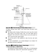
Figure 33
The connection of 120
Ω
termination resistor: The termination
resistor is ready on the Protocol PCB. There are two kinds of
connection. Refer to the Protocol PCB jumper setting form
(refer to Picture 2,3).
1) In the Picture it is the factory default connection. The jumper is
seated on Pin2&Pin3 and the termination resistor is not
connected.
2) when connecting the 120
Ω
termination resistor, user should
plug the jumper on Pin1&Pin2. and the termination resistor is
connected.
4. Problems in practical connection
In some circumstances user adopts a star configuration in practical
connection. The termination resistors must be connected to the two
equipment that are farthest away from each other, such as
equipment 1# and 15# in Picture 34. As the star configuration is not
in conformity with the requirements of RS485 standards, problems
such as signal reflections, lower anti-interference performance
arise when the cables are long in the connection. The reliability of
control signals is decreased with the phenomena that the dome
does not respond to or just responds at intervals to the controller,
or does continuous operation without stop (refer to Picture 34).
-33333333
33
Summary of Contents for VC-EX861
Page 41: ...37373737 37...
Page 42: ...CCTV SYSTEM...


