


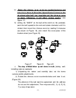


Install the ball on the bracket (Figure 12)
.
6)
Trip wire to give alarm marking (Figure 13 ),
System pilot
wire marking(Figure 14)
1
RED1:ALARM- 1
IN
ORANGE 2:ALARM- 2
IN
YELLOW 3:ALARM- 3
IN
GREEN 4:ALARM- 4
IN
BLACK 5: ALM IN COM
WHITE 6: ALARM OUT COM
BLUE 7: ALARM NO OUT
PINK 8: ALARM NC OUT
Figure 13
CONNECTOR
RED CONNECTOR
( POWER IN)
BLACK
( RS485 CONTROL IN)
VIDEO OUT
RED LINE( AC24V IN)
BLACK LINE( AC24 V IN)
ORANGE LINE (RS485+)
YELLOW LINE( RS485- )
Figure 14
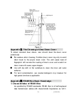
7)
Insert attachment plug in aluminum alloy into socket D2
(Figure 15) . According the fig of D3 to connection. As show of fig47
when dome identify the alarm signal, that will set according the
program immediately, then startup camera, switching the image of
alarm field to main monitor. Surveillance the alarm preset, then record
it in time. Fig16 is connection of alarm control
8)
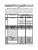
Input of alarm: Input signal of switch type, any other
input signal will damage dome. When multi-channel with alarm
signal, dome will respond one by one, the removed time is two
-20202020
20
Summary of Contents for VC-EX861
Page 41: ...37373737 37...
Page 42: ...CCTV SYSTEM...


