17
+
+
SYS
0V
RST
RUN
l/0
MS
NS
BT
24V
SD
RESET
STOP
RUN
U6
U5
U4
U3
U2
U1
‒
‒
‒
+
S S
A
B
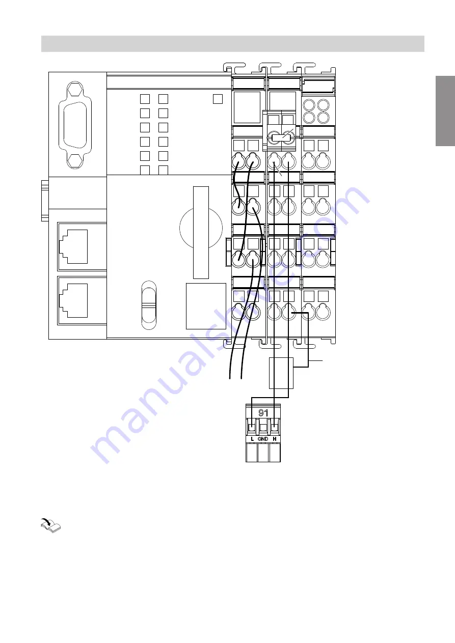
Fig. 9
A
CAN bus shield
B
Plug
lA
for controlling the heat generator (stand-
ard delivery of the gateway)
Installation and service instructions for heat gen-
erator control unit
Installation sequence
Establishing the CAN bus connection
(cont.)
6175460
Installation


