piping system at test pressures equal to or less than 14˝
w.c. (3.5 kPa).
Unions and manifold have been factory-tested. Leak
test must be repeated during initial trial operation of
burner by mechanical contractor.
Never check for gas leaks with an open flame. Use
approved liquid spray solution for bubble test. Follow
Fig. 14 whenever gas valve is replaced.
Proper piping practice
Support piping by proper suspension method. Piping
must not rest on or be supported by boiler.
7.4
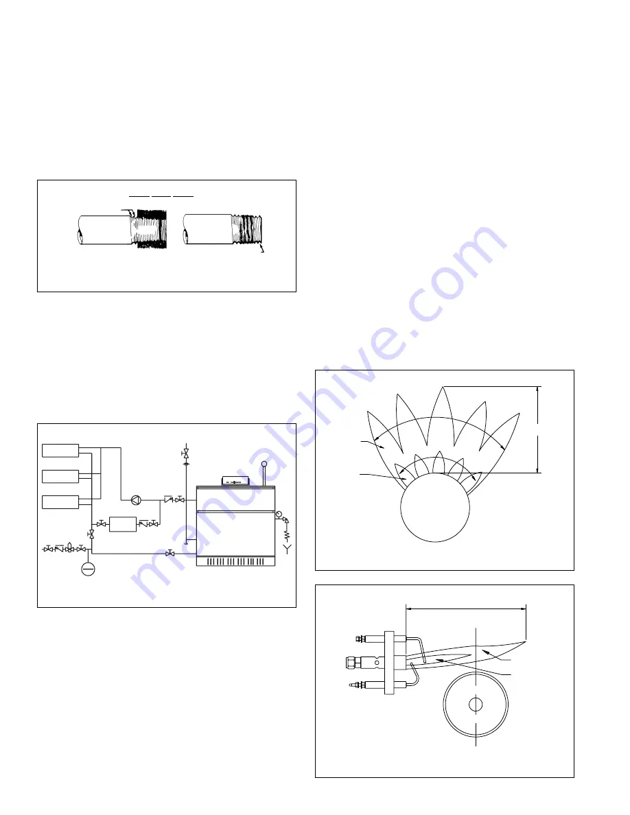
Boiler piping in heating/cooling application
The boiler, when used in connection with a refrigeration
system, must be installed so the chilled medium is
piped in parallel to the boiler with appropriate valves to
prevent the chilled medium from entering the boiler
(Fig. 15).
The boiler piping system of a hot water heating boiler
connected to heating coils located in air handling units
where they may be exposed to refrigerated air
circulation must be equipped with flow control valves or
other automatic means to prevent gravity circulation of
the boiler water during the cooling cycle.
Check installation instructions of chiller manufacturer
carefully for additional requirements.
Cooling season starts: Close valve V1 and open
valve V2.
Heating season starts: Close valve V2 and open
valve V1.
A metal tag should be attached to these valves as to
purpose.
Note:
In the above system, the circulating pump must be
operated from a separate on/off switch – not from the
pump aquastat on the boiler!
7.5
Main burner
Proper flame:
Upper main flame cone with light
orange coloring, sharply defined
individual flames.
Underfired:
Lazy-burning main flame cone,
mushy flame appearance throughout,
smaller flame sizes than in Fig. 16.
Overfired:
Increased burner noise, higher flame
sizes than Fig. 16.
7.6
Pilot burner
Proper flame:
Upper main flame cone with light orange
coloring, sharply defined individual flame.
12
Fig. 14
Gas piping into gas valve
Fig. 15
Boiler piping in a heating/cooling application
Heating/
cooling unit
Water
chiller
Heating/
cooling unit
Heating/
cooling unit
V
FC AFV
V
V2
CP
FC
V
FC
V
PRV
V1
Fig. 16
Front view – single burner
Main flame cone
Inner flame cone
Light blue
Blue
Burner
7˝
Fig. 17
Side view – pilot burner
6˝
(150mm)
Ionization
electrode
Pilot
burner
Ignition
electrode
Main burner
Orange outer
flame cone
Blue inner
flame cone
2 imperfect
threads
Thread pipe correct length, leave 2 end threads bare.
Use moderate amount of dope
Pipe
Control
Proper piping practice


