background image

10

A

5.

3.

4.

2.

1.

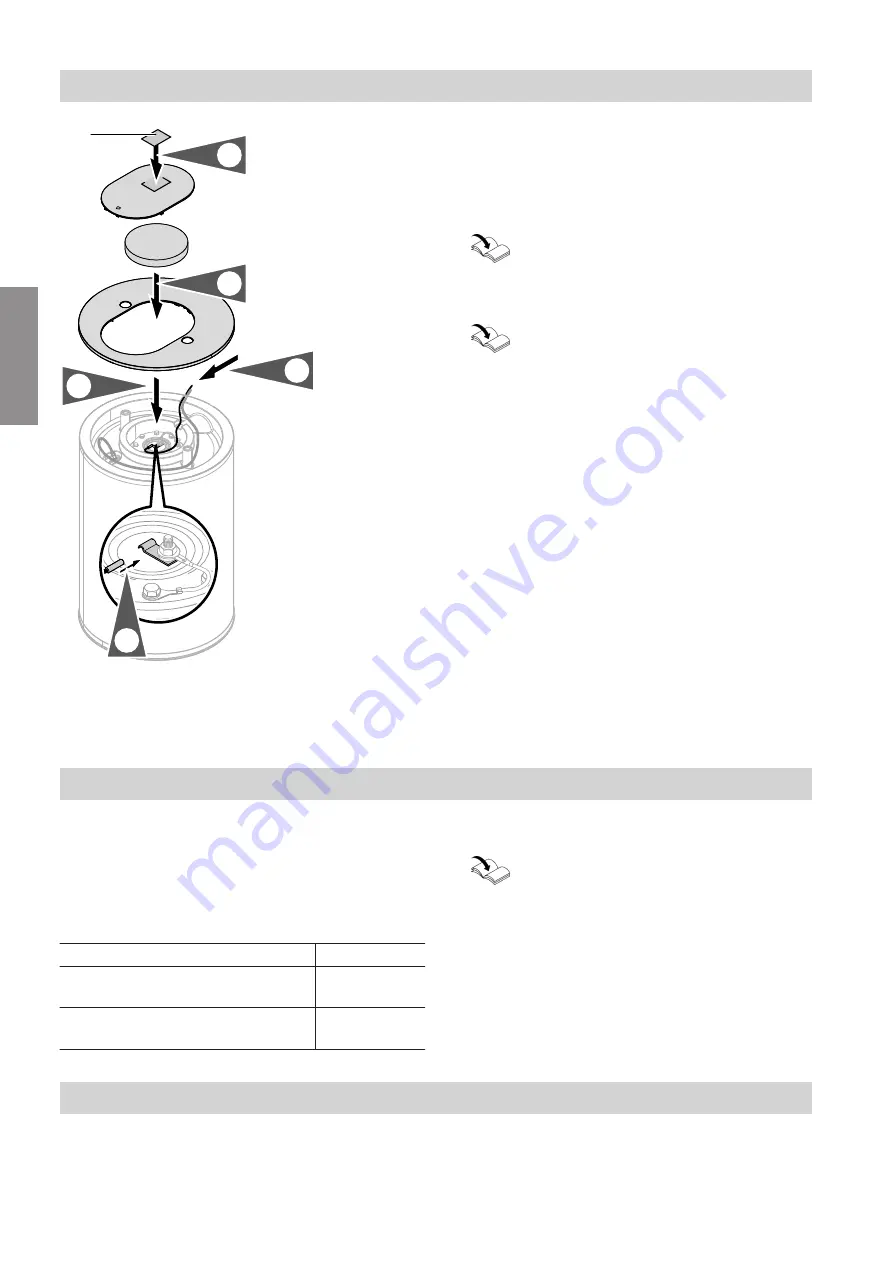
Fig. 4

A

Type plate

1. 

Route the thermometer lead through the groove in
the flange rim.

2. 

Insert the thermometer sensor as far as it will go
into the clamping bracket.

Installation instructions, casing for covering
connecting leads/cables

6. 

Secure the thermometer (accessory) to the wall.

Installation instructions for wall thermometer

Connections on the heating water side

Connect all pipework with detachable fittings.

Seal any connections that are not required with red
brass caps.

Adjust the temperature controller and high limit
safety cut-out so that the DHW temperature in the
DHW cylinder does not exceed 95 °C.

Permissible temperature

160 °C

Permissible operating pressure

10 bar

(1.0 MPa)

Test pressure

16 bar

(1.6 MPa)

1. 

Connect the pipes on the heating water side:

Connection set installation instructions

2. 

Only for heating water flow temperatures in excess
of 110 °C and if the system is not equipped with a
high limit safety cut-out: Install an additional type-
tested high limit safety cut-out.
For this, use a TR/HLSC combination device (tem-
perature limiter and high limit safety cut-out).

Connections on the DHW side

For connections on the DHW side, observe
DIN 1988 and DIN 4753 (

c

: SVGW regulations).

Seal in the drain valve at the drain connection and
check its function.

Connect all pipework with detachable fittings.

Seal any connections that are not required with red
brass caps.

Installation sequence

Thermometer sensor (if supplied), closing the appliance

6150560

Installation

Summary of Contents for VITOCELL 100-W

Page 1: ...Installation and service instructions for contractors VIESMANN Vitocell 100 W Type CUGA DHW cylinder 100 l VITOCELL 100 W 6150560 GB 1 2020 Please keep safe ...

Page 2: ...nstallation regulations Statutory regulations for the prevention of accidents Statutory regulations for environmental protection Codes of practice of the relevant trade associations Relevant country specific safety regu lations Working on the system Isolate the system from the power sup ply e g by removing the separate fuse or by means of a mains isolator and check that it is no longer live Safegu...

Page 3: ... work Repair work Please note Repairing components that fulfil a safety function can compromise the safe operation of the system Replace faulty components only with genuine Viessmann spare parts Auxiliary components spare and wearing parts Please note Spare and wearing parts that have not been tested together with the system can compromise its func tion Installing non authorised com ponents and ma...

Page 4: ...uence Cylinder temperature sensor anode connection 9 Thermometer sensor if supplied closing the appliance 10 Connections on the heating water side 10 Connections on the DHW side 10 Safety valve 11 Connecting the equipotential bonding 12 4 Commissioning inspec tion maintenance Steps commissioning inspection and maintenance 13 5 Commissioning service reports 17 6 Specification 18 7 Disposal Final de...

Page 5: ...teps required during inspection Not required during inspection Steps required during maintenance Not required during maintenance Intended use The appliance is only intended to be installed and operated in sealed unvented systems that comply with EN 12828 DIN 1988 or solar thermal systems that comply with EN 12977 with due attention paid to the associated installation service and operating instruc ...

Page 6: ...0 l Colour White Suitable for systems conforming to DIN 1988 EN 12828 and DIN 4753 Inspection and maintenance DIN 1988 requires a visual inspection and if neces sary cleaning no later than 2 years after the cylinder has been commissioned and thereafter according to requirements Note We additionally recommend checking the function of the protective magnesium anode annually This func tion check can ...

Page 7: ...7 2 1 4x 5 8 9 6 7 3 4 Fig 1 Preparing for installation Unpacking the DHW cylinder 6150560 Installation ...

Page 8: ...t with naked flames Exercise caution when welding and brazing Please note To prevent material losses install the DHW cyl inder in a room free from draughts and risk of frost If the location is not frost free drain the DHW cylinder when it is not in use Use the adjustable feet to level the DHW cylinder Note Only use one or two of the adjustable feet to level the DHW cylinder At least one of the adj...

Page 9: ... Note Push through the thermal insulation to route the sensor lead through the opening Note Never wrap insulating tape around the sensor 5 Insert the cylinder temperature sensor into the sen sor well as far as it will go 6 Secure sensor lead with strain relief sleeve Installation sequence Cylinder temperature sensor anode connection 6150560 Installation ...

Page 10: ...rature 160 C Permissible operating pressure 10 bar 1 0 MPa Test pressure 16 bar 1 6 MPa 1 Connect the pipes on the heating water side Connection set installation instructions 2 Only for heating water flow temperatures in excess of 110 C and if the system is not equipped with a high limit safety cut out Install an additional type tested high limit safety cut out For this use a TR HLSC combination d...

Page 11: ...lve as protection against overpres sure Permissible operating pressure 10 bar 1 0 MPa The safety valve must have the following connection diameter R DN 15 max heat input 75 kW If the heat input of the DHW cylinder exceeds 75 kW select an appropriately rated safety valve for the heat input see E DIN 1988 200 Install the safety valve in the cold water line Ensure it cannot be shut off from the DHW c...

Page 12: ...r local power supply utility and VDE or local regulations c Connect the equipotential bonding in accordance with the requirements stipulated by your local power supply utility and current SEV or local regulations Installation sequence Connecting the equipotential bonding 6150560 Installation ...

Page 13: ...on 4 Checking the anode earth current with an anode tester 14 5 Cleaning the inside of the DHW cylinder 14 6 Checking and replacing the protective magnesium anode 15 7 Returning the DHW cylinder to use 16 8 Checking the connections on the water side for tightness Commissioning inspection maintenance Steps commissioning inspection and maintenance 6150560 ...

Page 14: ... 1 Push down oval cover A and remove it 2 Remove flange insulation B 3 Remove thermometer sensor C if available 4 Remove earth cable D from tab E 5 Connect tester in series between earth cable D and tab E Current 0 3 mA Protective magnesium anode is OK Current 0 3 mA or no current at all Inspect the protective magnesium anode visually see page 15 Cleaning the inside of the DHW cylinder Danger Unch...

Page 15: ...quipment to clean the inside 5 Use a chemical cleaning agent to remove hard deposits that cannot be removed with a high pres sure cleaner Please note Cleaning agents containing hydrochloric acid will attack the DHW cylinder material Never use such cleaning agents Danger Cleaning agent residues can cause poison ing Always observe the information provided by the cleaning agent manufacturer 6 Fully d...

Page 16: ...Max torque 25 Nm 4 Push earth cable C onto tab D 5 Fit thermometer sensor E if available 6 Fill the DHW cylinder on the DHW side 7 Tighten the flange cover Max torque 25 Nm 8 Insert flange insulation G and fit oval cover F Checking the connections on the water side for tightness Commissioning inspection maintenance Returning the DHW cylinder to use 6150560 ...

Page 17: ...Maintenance service Date By Maintenance service Maintenance service Maintenance service Date By Maintenance service Maintenance service Maintenance service Date By Maintenance service Maintenance service Maintenance service Date By Commissioning service reports Commissioning service reports 6150560 Service ...

Page 18: ...18 Product characteristics Standby heat loss Standard parameter to EN 12897 2016 Qst at 45 K temp differential kWh 24 h 1 24 Specification Specification 6150560 Service ...

Page 19: ...stem are not part of ordi nary household waste For decommissioning the system isolate the system from the power supply and allow components to cool down where appropriate All components must be disposed of correctly Disposal Final decommissioning and disposal 6150560 Appendix ...

Page 20: ...the serial number the full Declaration of Con formity can be found on the following website www viessmann co uk eu conformity Viessmann Limited Hortonwood 30 Telford Shropshire TF1 7YP GB Telephone 44 1952 675000 Fax 44 1952 675040 E mail info uk viessmann com Viessmann Werke GmbH Co KG D 35107 Allendorf Telephone 49 6452 70 0 Fax 49 6452 70 2780 www viessmann com 6150560 Subject to technical modi...

Reviews: