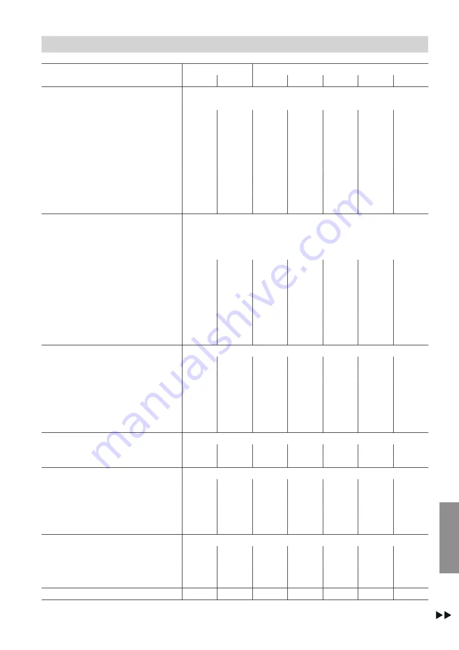
background image

63

Type BW

1-stage 301.

2-stage 302.

CS090

CS120

CS090

CS110

CS140

CS180

CS230

Electrical values, heat pump


Rated voltage, compressor


3/PE 400 V/50 Hz

Compressor rated current
(B0/W35)

A

34.7

42.8

19.0

each

22.3

each

28.3

each

34.7

each

42.8

each

Starting current, compressor
(with starting current limiter)

A

155.0

204.0

87.0

each

112.5

each

136.0

each

155.0

each

204.0

each

Starting current, compressor
with stalled armature

A

310.0

408.0

174.0

each

225.0

each

272.0

each

310.0

each

408.0

each

Heat pump fuse protection
(compressor and consumer)

A

80

100

80

100

125

160

200

Max. operating current, com-
pressor

A

65.4

82.6

68.0

80.0

97

130.8

165.2

Electrical values, control unit


Rated voltage


1/N/PE 230 V/50 Hz

Fuse protection (internal)


1 x B16A

Fuse


6.3 AH (slow)/250 V

Rated output

W

1000

1000

1000

1000

1000

1000

1000

Max. power consumption,
stage 1

W

25

25

25

25

25

25

25

Max. power consumption,
stage 2

W


20

20

20

20

20

Max. power consumption,
stages 1 and 2

W


45

45

45

45

45

Protection class/IP rating


IP 20

IP 20

IP 20

IP 20

IP 20

IP 20

IP 20

Refrigerant circuit


Refrigerant


R410A

R410A

R410A

R410A

R410A

R410A

R410A

Refrigerant charge

kg

15.8

17.5

14.8

16.5

24.8

31.5

41.5

Permiss. operating pressure,
low pressure side

bar

18

18

18

18

18

18

18

Permiss. operating pressure,
high pressure side

bar

45

45

45

45

45

45

45

Number of compressors


1

1

2

2

2

2

2

Permiss. operating pressure


Primary circuit

bar

6

6

6

6

6

6

6

Secondary circuit

bar

6

6

6

6

6

6

6

Dimensions


Total length

mm

1343

1343

1343

1343

1932

1932

1932

Total width

mm

911

911

911

911

911

911

911

Width without side panels
(transport dimension)

mm

850

850

850

850

850

850

850

Total height

mm

1650

1650

1650

1650

1650

1650

1650

Connections


Primary circuit flow and return
(brine side)

Ø

3"

(DN 80)

3"

(DN 80)

3"

(DN 80)

3"

(DN 80)

3"

(DN 80)

3"

(DN 80)

3"

(DN 80)

Secondary circuit flow and re-
turn (heating side)

Ø

2½"

(DN 65)

2½"

(DN 65)

2½"

(DN 65)

2½"

(DN 65)

2½"

(DN 65)

2½"

(DN 65)

2½"

(DN 65)

Weight

kg

770

870

720

910

1180

1280

1425

Specification

Specification, Vitocal 300-G

 (cont.)

5789 986 GB

Appendix

Summary of Contents for BW 30 .CS Series

Page 1: ...ructions for contractors Viesmann Vitocal 300 G Pro SPS Type BW 301 CS090 to 302 CS230 82 8 to 296 0 kW Heat pump single and two stage For applicability see the last page VITOCAL 300 G PRO SPS 5789 98...

Page 2: ...ant trade associations All relevant safety regulations as defined by DIN EN DVGW VDE and locally applicable standards a NORM EN and VE c SEV SUVA SVTI SWKI and SVGW Working on the system Isolate the s...

Page 3: ...with the system can compromise its function Installing non authorised components and making non approved modifications or con versions can compromise safety and may inva lidate our warranty For repla...

Page 4: ...connections 24 Connecting the Vitocal 300 G 25 Fitting the Victaulic couplings 26 Connecting the primary circuit 27 Connecting the secondary circuit 27 Electrical connections 28 Routing cables to the...

Page 5: ...issioning service reports Commissioning report 58 10 Specification Specification Vitocal 300 G 61 11 Appendix Heat pump commissioning request 65 12 Final decommissioning Dismantling disposal 66 13 Cer...

Page 6: ...X X X X X Installation X X X Commission ing X X X X Operation X X Maintenance repair shut down X X X X X Dismantling removal col lection X X X X X Disposal X X X Electrical connections Danger Electrom...

Page 7: ...hreatening crushing or break ages if they fall or are dropped Use suitable ropes slings and lifting gear when installing dismantling compressors and heat exchangers for example Wear appropriate protec...

Page 8: ...ehind sharp edges from the metal retaining tabs that can lead to life threatening injuries Finish and seal the edges appropriately before installation Note Damage to the surfaces of the casing can lea...

Page 9: ...or In conjunction with a tool Clean the sur face Dispose of component correctly Dispose of component at a suitable collec tion point Do not dispose of component in domestic waste The steps in connect...

Page 10: ...y by authorised and trained personnel Product information Vitocal 300 G Pro SPS Heat pump Vitocal 300 G Pro SPS type BW Medium Brine water Single stage heat pumps 301 CS090 301 CS120 2 stage heat pump...

Page 11: ...damage on the delivery note and notify the haulage contractor Lifting gear such as slings and cross beams must be provided on site The lifting capacity of each sling and that of the cross beam must be...

Page 12: ...tion e g 2 or 3 layers of corrugated cardboard D Cross beam to relieve the load on the frame Note Lifting with belt straps is only permitted without the side front or back panels fitted Handling by fo...

Page 13: ...note Overloading the floor can result in damage to the building structure Observe the permissible floor load Take the weight of the appliance into account Weight Type Weight in kg BW 301 CS090 770 BW...

Page 14: ...ll clearance 80 mm B When using hydraulic connection accessories connection set and Victaulic flange adaptor set 2 or 3 1000 mm On site hydraulic connections 600 mm C Clearances for installation and m...

Page 15: ...n screed C Top edge unfinished floor D Impact sound insulation as per regulations E Pressure tested sound insulation layer approx 10 to 20 mm F Heat pump Pressure points of the adjustable heat pump fe...

Page 16: ...e BW 301 CS090 to BW 301 CS120 BW 302 CS090 and BW 302 CS110 850 1343 1650 911 1241 644 436 1126 368 343 200 Fig 8 A flow primary circuit inlet Victaulic 3 DN 80 B flow secondary circuit outlet Victau...

Page 17: ...ctaulic 2 DN 65 E Low voltage 50 V F Power supply 230 V 50 Hz G Power supply 400 V 50 Hz Note The width of the heat pump is given with and without side panels The dimensions without side panels are th...

Page 18: ...ic connections General hydraulic scheme DHW Fig 10 Black lines master circuit grey lines slave circuit DHW circulation Preparing for installation Hydraulic connection requirements cont 5789 986 GB Ins...

Page 19: ...ircuit 9 Expansion vessel primary circuit residual heat circuit qP Geothermal probe manifold qQ Safety assembly primary circuit qW Pressure switch primary circuit qE Frost stat qR System separation gr...

Page 20: ...trol requires additional con tactor w E 3 way diverter valve heating cooling w R Heating circuit pump HC2 w T 3 way mixer e P Underfloor heating circuit cooling circuit M3 e Q Flow temperature sensor...

Page 21: ...21 Levelling the heat pump Fig 11 Site and level the heat pump horizontally as described on page 13 onwards Installation sequence Siting the heat pump 5789 986 GB Installation...

Page 22: ...ort brackets are not removed they cause vibrations and excessive noise Remove all 4 transport brackets fully from below and dispose of them correctly Fig 12 A Transport locking screws Installation seq...

Page 23: ...de panels and kicking plates Note After fitting the back panel make the hydraulic and electrical connections See following chapter 1 2 3 3 4 2x 6x 5 Fig 13 Installation sequence Siting the heat pump c...

Page 24: ...3 DN 80 B flow secondary circuit outlet Victaulic 2 DN 65 C return primary circuit outlet Victaulic 3 DN 80 D return secondary circuit inlet Victaulic 2 DN 65 E Low voltage 50 V F Power supply 230 V...

Page 25: ...pling 2 secondary circuit C Flexible connection pipe 3 primary circuit with anti vibration elements D Flexible connection pipe 2 secondary circuit with anti vibration elements E Hydraulic line fixings...

Page 26: ...line fixings Fitting the Victaulic couplings Fig 17 1 Clean all Victaulic connections 2 Open Victaulic coupling B around 1 cm 3 Push Victaulic coupling B with inserted gasket as far as it will go onto...

Page 27: ...seated correctly Make line entries airtight 4 Insulate primary lines inside the building with ther mally insulating and vapour diffusion proof materi als 5 Fill the primary circuit with Viessmann heat...

Page 28: ...ult e g if a wire becomes detached the wires cannot drift into the adjacent voltage area When routing on site power cables observe the loca tion of the cable entries into the appliance through the bac...

Page 29: ...le wire ferrule Wiring chamber front Fig 19 Note Diagram without terminal covers see also page 56 A Power supply power circuit compressor 3 x 400 V 50 Hz with ON OFF switch B Circuit breaker LV HRC fu...

Page 30: ...CD3OEM C Contactors for primary pump secondary pump and options D Terminal strip for external heat pump components E Relay control options F Terminal strip for internal heat pump components Installati...

Page 31: ...values Max voltage 250 V Max switching current 4 A AC1 Circuit protection from load fuse 5FC1 observe the maximum total current of 16 A Terminals Function Explanation 13X0 Circulation pump evaporator...

Page 32: ...hing current 9 A AC3 25X1 Circulation pump external heat source Connection values Max output 4000 W 2200 W Voltage 400 V 230 V Max switching current 9 A AC3 40X0 Circulation pump residual heat Connect...

Page 33: ...xing valve external heat source Connection values Max output 180 VA Voltage 24 VAC DC 0 10 V Terminals Function Explanation 22X0 Diverter valve DHW heating Connection values Voltage 24 VDC Max switchi...

Page 34: ...er valve 1 3 way diverter valve cooling mode Connection values Voltage 24 VDC Max switching current 4 A 36X2 Diverter valve 2 2 way shut off valve source Connection values Voltage 24 VDC Max switching...

Page 35: ...ations Multi stage enabling input 1 one stage 19X6 External multi stage enabling input 2 Function depends on the configuration For complete third party control without set value External demand 2 For...

Page 36: ...ppliance All sensor and signal leads 0 10 V must be shielded with copper braiding and have a mini mum cross section of 0 5 mm2 Specified lead type CV Sensors internal Terminals Analogue inputs and out...

Page 37: ...m Danger Incorrectly executed electrical installations can result in injuries from electrical current and dam age to the appliance Connect the power supply and implement all safety measures e g RCD ci...

Page 38: ...routing in the vicinity of heating pipes or encapsulated routing the cross sections and max cable lengths must be recalculated on site Power circuit 400 V on site control circuit 230 V factory fitted...

Page 39: ...abled Note Observe the technical connection conditions of the rel evant power supply utility Electronic soft starter type SMC Electronic soft starter functions Monitoring the compressor mains feed Red...

Page 40: ...SS OPEN LOAD 5 PHASE IMBALANCE 6 SHORTED SCR 7 TEST L1 L2 L3 T1 T2 T3 Fig 21 Number of flashes 1 Overload 2 Excess temperature 3 Phase reversal 4 Phase loss motor not connected 5 Phase asymmetry 6 Sho...

Page 41: ...the programming unit into place in the open ing and check for firm seating Securely lean the front panel against the heat pump Closing the heat pump Danger The absence of component earthing can resul...

Page 42: ...conductors been fitted Have all cable entries been correctly applied and sealed against moisture ingress Do all hydraulic connections have airtight sealing and insulation with thermal and vapour diffu...

Page 43: ...44 5 Filling and venting on the secondary side 45 6 Checking expansion vessels and primary circuit secondary circuit pressure 45 7 Commissioning the system 45 8 Checking the electronic flow switch typ...

Page 44: ...on page 58 onwards Checking the refrigerant circuit for leaks Check the floor area valves and all visible solder joints for traces of oil Note Traces of oil indicate a leak in the refrigerant circuit...

Page 45: ...p with water if required Minimum system pressure 0 8 bar 80 kPa Permiss operating pressure 6 bar 0 6 MPa Checking expansion vessels and primary circuit secondary circuit pressure Observe engineering i...

Page 46: ...her than nominal flow rate If necessary carry out an operating display adjustment high flow balancing see below for example if a circulation pump had to be sized for higher flow rates LED 0 flashes gr...

Page 47: ...and hold for around 5 s until LED 9 flashes 3 Release Fitting the top panel and front panel closing the heat pump See page 41 Instructing the system user The system installer should hand the operating...

Page 48: ...will go Hydraulic line is touching the heat pump casing back panel Hydraulic line not connected free of load and torque stress Anti vibration elements for hydraulic connection are missing Connection l...

Page 49: ...e and ensure it cannot fall over 4 Carefully remove the top panel see page 42 Overview of electrical components See page 29 onwards Overview of internal components Vitocal 300 G Fig 25 Example type BW...

Page 50: ...he heat pump at the on site drain valve on the primary secondary side Checking sensors Sensor Test element Connection installation position Outside temperature sensor Flow temperature sensor secondary...

Page 51: ...pecification Power circuit fuse system components see sepa rate Connection and wiring diagram Danger Contact with live components can lead to seri ous injury from electric current Before working on th...

Page 52: ...52 Repairs Checking fuses cont 5789 986 GB Maintenance...

Page 53: ...53 The following details are required when ordering parts Serial no see type plate Position number of the part from this parts list Parts lists Ordering parts 5789 986 GB Components...

Page 54: ...2 0014 0001 0026 0024 0004 0006 0007 0007 0016 0011 0011 0012 0015 0001 0010 0021 0018 0019 0020 0003 0009 0008 0022 0022 0023 0027 0005 0013 0017 0025 Fig 27 Parts lists Parts section 1 5789 986 GB C...

Page 55: ...bly 0012 Dryer bracket 0013 Temperature sensor Pt1000 2 or 4 m 0014 Oil compensation line 0015 Sight glass for soldering 0016 Electronic expansion valve 0017 Sensor well with gasket 0018 Motor overloa...

Page 56: ...33 0031 0033 0031 0032 3x 0032 0034 0034 0035 0033 0039 0036 0038 0037 0043 0042 0047 4x 0052 0049 0050 0051 0053 0055 0054 0046 0045 17x 17x 11x 0048 0049 0050 0051 0044 0041 0040 0040 0044 0044 0049...

Page 57: ...tension module 0038 SPS connector 0039 Ethernet switch 0040 Circuit breaker 0041 Circuit breaker 0042 Circuit breaker 0043 Circuit breaker 0044 Neutral conductor isolator 0045 Base for relay 0046 Rela...

Page 58: ...Overheating set value Config heat pump param eters Evaporator pump advance runtime primary circuit Config heat pump param eters Fault primary circuit flow response delay System groundwater heat sourc...

Page 59: ...ng circuit 1 room standard temperature day Heating circuit 2 room standard temperature day Heating circuit 3 room standard temperature day System heating circuits heating circuit1 curve night standard...

Page 60: ...change service password required Group 1 cooling factor room flow temperature Group 2 cooling factor room flow temperature Group 3 cooling factor room flow temperature System cold water set val ue fi...

Page 61: ...flow rate kPa 6 0 6 5 7 5 7 6 9 0 9 3 10 0 Max flow temperature C 20 20 20 20 20 20 20 Min flow temperature C 5 5 5 5 5 5 5 Min flow temperature ice store at nominal flow rate C 10 10 10 10 10 10 10...

Page 62: ...7 7 Heating water secondary circuit Content l 18 4 23 1 18 4 23 1 28 7 35 1 50 3 Nominal flow rate m3 h 20 0 25 7 19 0 24 9 31 1 40 2 51 3 Pressure drop at nominal flow rate 5 K kPa 25 0 28 0 22 0 26...

Page 63: ...0 20 20 20 Max power consumption stages 1 and 2 W 45 45 45 45 45 Protection class IP rating IP 20 IP 20 IP 20 IP 20 IP 20 IP 20 IP 20 Refrigerant circuit Refrigerant R410A R410A R410A R410A R410A R410...

Page 64: ...914 2 weighted to tal sound power level at B0 3 K W35 5 K At rated heating output dB A 63 67 57 63 66 65 69 ErP SCOP LT 5 16 5 22 5 13 5 1 5 1 5 17 5 23 etas LT 198 201 197 196 196 199 201 SCOP HT 3 6...

Page 65: ...uits fully installed and filled Electrical installation completed Hydraulic lines fully thermally insulated All windows and external doors airtight Geothermal probes well and connection lines fully in...

Page 66: ...t be carried out by type The dismantling of refrigeration systems may only be carried out by qualified professio nals If permissible components marked with the Green Dot symbol can be disposed of via...

Page 67: ...12 EN 61 000 6 4 2011 09 EN 50 090 2 2 2007 11 EN 62233 2008 11 EN 55011 2011 EN ISO 12100 2011 03 EN 60 335 2 40 2014 01 EN 292 1991 11 EN 60 335 1 with A1 2012 10 EN 378 2012 08 EN 61 000 6 2 2011 0...

Page 68: ...tandards DIN 8901 2002 12 EN 61 000 6 4 2011 09 EN 50 090 2 2 2007 11 EN 62233 2008 11 EN 55011 2011 EN ISO 12100 2011 03 EN 60 335 2 40 2014 01 EN 292 1991 11 EN 60 335 1 with A1 2012 10 EN 378 2012...

Page 69: ...cuit Curve 50 Flow temperature sensor secondary circuit Curve 50 Fuses checking 51 H Heat pump closing 41 47 Heat pump draining 50 Heat pump opening 44 Heat pump levelling 21 Heat pump siting 21 Heat...

Page 70: ...ressure switch 49 Schrader valve 50 Seal ring replacement 44 45 Secondary circuit filling 45 Secondary circuit filling and venting 45 Secondary circuit connection 27 Sensors 49 Sensors checking 50 Sig...

Page 71: ...71 5789 986 GB...

Page 72: ...essmann Limited Hortonwood 30 Telford Shropshire TF1 7YP GB Telephone 44 1952 675000 Fax 44 1952 675040 E mail info uk viessmann com Viessmann Werke GmbH Co KG D 35107 Allendorf Telephone 49 6452 70 0...

Reviews: