Operation
Vidikron Vision Model 65/Model 75 Installation/Operation Manual
61
• Advanced Color Enhance (ACE):
Use the Advanced Color Enhance (ACE) controls to
customize the stored color space characteristics. To do this, use the
or
button to
select a component color (Red, Green, Blue, Yellow, Cyan or Magenta).
For each component color, you can adjust the following:
•
Limit:
This slidebar adjusts the intensity – also known as
luminance
– of a given color.
•
Saturation:
This slidebar adjusts the color saturation level – the amount of that color in
a video image. Lower settings produce less saturated colors; a setting of “0” removes
that color from the image entirely. If the saturation is too high, that color will be
overpowering and unrealistic.
To restore the color space settings to their factory-default values, select Reset to Defaults
and press
ENTER
.
• Gamut:
Under most conditions, the White Balance and Advanced Color Enhance (ACE)
controls in the Calibration menu are adequate for producing accurate and realistic colors
from a variety of sources.
In rare cases, though, you may need more precise control over the Vision 65/75 display
color gamut (range). For example, you may require a unique color gamut for a given
projector or application.
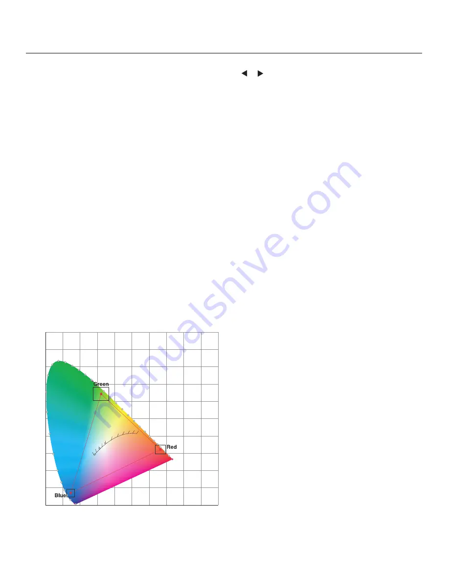
The Vision 65/75 enables you to define the precise hue of each primary color component
(white, red, green and blue) used to generate the millions of colors produced in displays.
You do this by specifying x/y coordinates and luminance values for each primary color
component.
The x and y coordinates for each color define its location on the standard CIE chromaticity
graph, shown in Figure 4-9. (CIE stands for “Commission Internationale de l’Éclairage”
(International Commission on Illumination), the organization responsible for color
measurement and management standards.)
Figure 4-9. CIE 1931 Chromaticity Diagram
0.0
0.1
0.2
0.3
0.4
0.5
0.6
0.7
0.8
0.9
1.0
0.0
0.1
0.2
0.3
0.4
0.5
0.6
0.7
0.8
0.9
1.0
x
y
2000
2222
2500
2857
3333
4000
5000
5714
6667
8000
10000
D50
D65
D93
Summary of Contents for Vision 65
Page 2: ......
Page 14: ...Table of Contents xiv Vidikron Vision Model 65 Model 75 Installation Operation Manual Notes...
Page 86: ...Serial Communications 70 Vidikron Vision Model 65 Model 75 Installation Operation Manual Notes...
Page 94: ...Specifications 78 Vidikron Vision Model 65 Model 75 Installation Operation Manual Notes...
Page 95: ......
Page 96: ...1 888 4 VIDIKRON Fax 503 748 8161 www vidikron com SERIAL NUMBER 020 0715 02 Rev A March 2008...


