background image

Operation

54

Vidikron Vision 

8

5 Owner’s Operating Manual

PRE

L

IMINAR

Y

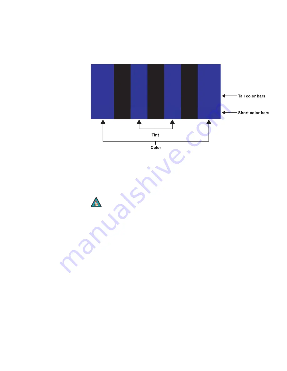
Select Color and press 

ENTER

. While looking at the color bar pattern through a blue filter, 

adjust the color saturation level until the outermost (gray and blue) color bars appear to be a 
single shade of blue: 

Tint: 

Tint or “hue” is essentially the ratio of red to green in the color portion of the image. 

When tint is decreased, the image appears redder; when it is increased the image appears 
greener. To set the tint, select Tint and press 

ENTER

. While looking at the color bar pattern 

through a blue filter, adjust the tint level until the cyan and magenta color bars (on either 
side of the green bar) appear to be a single shade of blue. 

Like the brightness and contrast controls, the color and tint controls are 
interactive. A change to one may require a subtle change to the other in 
order to achieve the optimum setting. 

gray

yellow

cyan

gr

een

magenta

re

d

blue

Note

Summary of Contents for 85

Page 1: ...1080p DLP PROJECTORS Vision 85 Vision 85 CineWide Vision 85 CineWide with AutoScope 85 VERSION 1 0 O W N E R S O P E R A T I N G M A N U A L ...

Page 2: ......

Page 3: ...r normal maintenance This Limited Warranty does not cover cabinets or any appearance items failure resulting from accident misuse abuse neglect mishandling misapplication faulty or improper installation or setup adjustments improper maintenance alteration improper use of any input signal damage due to lightning or power line surges spikes and brownouts damage that occurs during shipping or transit...

Page 4: ...sibility to arrange for shipment of the product for repair These arrangements must be made through the selling Vidikron Dealer If this is not possible contact Vidikron directly for a Return Authorization number and shipping instructions Vidikron will return product transportation prepaid in the United States unless no product defect is discovered In that instance shipping costs will be the respons...

Page 5: ..._______________________________________ Model Purchased Date ____________________________________________________________________________________________________________ Serial Number ____________________________________________________________________________________________________________ Vidikron Authorized Dealer Name ___________________________________________________________________________...

Page 6: ...12V trigger only outputs DC 12V signal for triggering Do not connect to any other power input or output This could cause damage to this unit 10 Only use accessories specified by Vidikron 11 Keep the packing material in case the equipment should ever need to be shipped 12 Unplug this projector during lightning storms or when it will not be used for an extended period of time 13 The lamp becomes ext...

Page 7: ...s and Benefits 4 Parts List 4 2 Controls and Functions 5 Vision 85 at a Glance 5 Vision 85 Rear Panel 7 VHD Controller Front Panel 8 VHD Controller Rear Panel 9 Outputs 9 Inputs 9 Vision 85 Remote Control Unit 11 Vision 85 Built In Keypad 14 3 Installation 15 Remote Control 15 Battery Installation 15 Notes on Remote Control Operation 15 Quick Setup 17 Installation Considerations 18 Installation Ty...

Page 8: ...cting a PC or Automation System to the VHD Controller 33 Connecting 12 Volt Trigger Outputs to External Equipment 34 Connecting an External IR Receiver to the VHD Controller 35 Connecting to AC Power 36 Turning on the Power 36 Adjusting the Picture Orientation 37 Primary Lens Adjustments 37 Focus and Zoom 37 Vertical Lens Shift 37 Installing and Adjusting the CineWide Anamorphic Lens 38 Anamorphic...

Page 9: ...just 65 Picture Adjust Advanced 67 White Balance 69 Information 69 Options 70 5 Maintenance and Troubleshooting 73 Lamp Replacement 73 Troubleshooting Tips 74 6 Serial Communications 77 RS 232 Connection and Port Configuration 77 Serial Command Syntax 77 7 Specifications 83 Vision 85 Specifications 83 VHD Controller Specifications 85 Vision 85 Dimensions 86 ...

Page 10: ...Table of Contents x Vidikron Vision 85 Owner s Operating Manual P R E L I M I N A R Y Notes ...

Page 11: ...nd Ceiling Mounting Rails Bottom View 26 3 10 Connecting the Projector to the VHD Controller 28 3 11 HDMI Source Connections 29 3 12 Digital DTV RGB or Component Video Connections 30 3 13 Analog RGB Connections 31 3 14 Composite S Video and Component Video Connections 32 3 15 RS 232 Control System Connection 33 3 16 12 volt Trigger Output Connections from VHD Controller 34 3 17 12 volt Trigger Out...

Page 12: ...R E L I M I N A R Y 4 4 Typical Color Bar Pattern for Adjusting Color Saturation and Tint 53 4 5 Typical Test Pattern for Adjusting Sharpness 55 4 6 OSD Menu Structure for Vision 85 1080i Digital or 1080p Sources 63 7 1 Vision 85 CineWide with AutoScope Dimensions 86 ...

Page 13: ...lcomes your comments about this manual Send them to info vidikron com Textual and Graphic Conventions Text Conventions The following conventions are used in this manual in order to clarify the information and instructions provided Remote and built in keypad button identifiers are set in upper case bold type for example Press EXIT to return to the previous menu Computer input commands you type and ...

Page 14: ...special significance They also provide supplemental information CAUTIONS alert users that a given action or omitted action can degrade performance or cause a malfunction WARNINGS appear when a given action or omitted action can result in damage to the equipment or possible non fatal injury to the user DANGER appears when a given action can cause severe injury or death Tip Note Caution WARNING DANG...

Page 15: ...al Imagix video processing is included for the most advanced video processing 1080p scaling and pristine image quality available The Vision Model 85 offers a broad array of video inputs including HDMI Discrete infrared IR and RS 232 control make custom installation seamless while discrete source and aspect ratio selection accommodate any automation control system For uncompromising widescreen repr...

Page 16: ... any items are missing or damaged please contact your Vidikron dealer or Vidikron Customer Service at 888 4VIDIKRON Vision 85 DLP Projector and VHD Controller Remote Control Unit and two 2 AAA size batteries AC Power Cords 2 RJ 11 Telephone Cable 50 feet 15 24 meters 9 64 Hex Wrench for lens adjustments Rack mount hardware for the VHD Controller Warranty information and registration card Vidikron ...

Page 17: ...s Operating Manual 5 P R E L I M I N A R Y 2 1 Vision 85 at a Glance Figure 2 1 shows the key Vision 85 components Figure 2 1 Vision 85 Front Top Side Bottom Rear View 2 Controls and Functions 11 9 10 6 3 4 5 5 2 1 11 12 8 7 9 ...

Page 18: ...o heat sensitive objects near it and that it is never blocked 6 CABLE OPENING Pass cables through this opening 7 INTAKE VENTS Cool air enters the projector through these vents To prevent overheating ensure that these vents are never blocked 8 ZOOM TAB Turn this tab to make the projected image larger or smaller 9 VIDIKRON LOGO You can rotate the logo to match the projector orientation inverted ceil...

Page 19: ...al DC power supply type jack Connection for a retractable screen screen masking or other 12 volt trigger activated equipment Outputs 12 volts 200 mA when the projector is turned on 5 WIRED IR 3 5 mm mini phono jack Not used To use an external infrared receiver or wired remote control with this projector connect it to the IR input on the VHD Controller see Figure 2 4 6 RS 232C INPUT RJ 11 female co...

Page 20: ...TTON Press once to toggle from standby mode to on mode Press it again to return to standby mode For a discrete on or off command you can use the direct access buttons on the remote control 2 IR SENSOR Receives IR commands from the remote 3 VACUUM FLUORESCENT DISPLAY Can be used instead of the On Screen Display OSD Displays currently selected menu or if no menu is selected the current source signal...

Page 21: ...080i 4 COMPONENT VIDEO RCA connectors Standard Definition 480i 576i Component YPrPb input This is the input for component video from sources such as DVD players Pb Pr Y Video 3 IR RS 232 Control S Video 1 S Video 2 HD1 HD2 1 2 R Pr G Y B Pb R Pr G Y B Pb H V HDMI 1 HDMI 2 HDMI Out H V TRIGGERS RS 232 Out CAUTION TO REDUCE THE RISK OF ELECTRIC SHOCK DO NOT REMOVE COVER NO USER SERVICEABLE PARTS INS...

Page 22: ...o the ComLink RS 232 input on the projector using the provided communication cable 9 IR Wired input from a wired remote control or infrared receiver It is a 3 5 mm mini phono jack wired as follows Ring 5V Tip IR Input Sleeve Ground 10 RS 232 CONTROL PORT A female 9 pin D sub connector for interfacing with a PC or home theater automation control system 11 POWER INPUT 100 to 240 VAC Connect the VHD ...

Page 23: ...1 P R E L I M I N A R Y 2 5 Vision 85 Remote Control Unit Figure 2 5 shows the Vision 85 remote control and the paragraphs that follow describe its functionality Figure 2 5 VHD Controller Vision 85 Remote Control 1 2 7 10 14 19 22 16 11 4 3 5 6 8 12 17 18 20 21 13 9 15 ...

Page 24: ...16 9 Likewise the LEFT and RIGHT buttons toggle through the different source inputs in this order LEFT Button HDMI 2 HDMI 1 HD RGB2 HD RGB 1 Component SD S Video 2 S Video 1 Composite RIGHT Button Composite S Video 1 S Video 2 Component SD HD RGB 1 HD RGB 2 HDMI 1 HDMI 2 6 RETURN EXIT Press this button to exit the current menu and return to the previous one or to cancel an operation 7 MENU Press t...

Page 25: ...eo input as the source or to enter the numeric character 3 15 HD 1 4 HD 2 7 Press to select a HD RGBHV or YPbPr component input or to enter the numeric character 4 or 7 16 HDMI 1 6 HDMI 2 8 Press to select a Digital Video input or to enter the numeric character 6 or 8 Aspect Ratio Selection Buttons Use these buttons to select an aspect ratio directly or to enter numeric characters as follows 17 16...

Page 26: ...or adjust settings 4 MENU Press MENU to display or hide the OSD menus for digital 1080i or 1080p sources 5 not used 6 STANDBY Press STANDBY to put the projector into standby mode 7 ON Press ON to turn the projector on or off Only trained service personnel should use the built in keypad Almost all projector configuration and operational tasks can be performed using the VHD Controller It is only nec...

Page 27: ...Control Operation The remote control can be used to control the Vision 85 within the ranges shown in Figure 3 1 Figure 3 1 Available Range of the Remote Control 3Installation 1 Do not mix an old battery with a new one or different types of batteries 2 If you will not use the remote control for a long time remove the batteries to avoid damage from battery leakage Note Component SD NTSC 480i 16 9 Ap...

Page 28: ...at there is nothing obstructing the infrared beam between the remote control and the IR receiver on the VHD Controller or projector If the effective range of the remote control decreases or it stops working replace the batteries with new ones Ambient conditions may possibly impede the operation of the remote control If this happens point the remote control at the VHD Controller or projector and re...

Page 29: ...es to the VHD Controller 29 6 Connect external controller to RS 232 port optional 33 7 Connect other home theater components to 12 volt trigger outputs optional 34 8 Connect the projector VHD Controller and AutoScope lens motor if present to power and turn on the system 36 9 For rear screen and or ceiling mount installations select the proper picture orientation 37 10 Primary lens adjustments proj...

Page 30: ...2 inputs Brightness Contrast Color level Tint Input position 63 through 71 Table 3 1 Installation Overview continued Table 3 2 Projector Installation Options Advantages Considerations Front Screen Floor Mount Installation Easy to set up Can be moved or changed quickly Easy to access Shares floor space with audience Front Screen Inverted Mount ceiling Installation Does not take up audience space Pr...

Page 31: ...projector should be positioned from the screen in order to project a focused image large enough to fill the screen Figure 3 2 Estimating Throw Distance Table 3 3 gives the throw ratios for the Vision 85 Vision 85 CineWide and Vision 85 CineWide with AutoScope Table 3 3 Throw Ratios for the Vision 85 Series Projector Model Throw Ratio with Primary Lens Only Throw Range in inches with 72 6x40 8 inch...

Page 32: ... If it is not possible to align the projector and screen as shown in Figure 3 3 you can use the lens shift controls to center the image on the screen Lens shift is generally expressed as a percentage of the screen height or width as shown in Figure 3 4 Figure 3 4 Vertical Lens Shift EXAMPLE ONLY Height Projection Distance Ceiling Ceiling Installation Screen Height Floor Lens Center Projection Dist...

Page 33: ...jector and mirror must be accurately set If you are considering this type of installation contact your dealer for assistance Figure 3 5 Folded Optics Other Considerations Other considerations and tips that can help improve your installation Keep the ambient temperature constant and below 35 C 95 F Keep the projector away from heating and or air conditioning vents Changes in temperature may cause d...

Page 34: ...oceed with Installing the Fixed CineWide Base Plate Vision 85 CineWide page 26 If you are installing a Vision 85 CineWide with AutoScope proceed as follows to install the AutoScope lens motor 1 Do not install the CineWide lens yet only the fixed CineWide baseplate or AutoScope lens motor You will install the CineWide lens after you install the projector and adjust the primary lens 2 Some component...

Page 35: ...85 CineWide with AutoScope Motor Assembly Exploded View Remove Projector Front Feet Place the projector upside down on a blanket or other soft surface Then remove the two feet at the front of the projector using a Phillips screwdriver 3 4 Screw Phillips Pan Head 10 32 x 1 2 12x 1 AutoScope Lens Motor 2 CineWide with AutoScope Ceiling Mount Adapter Projector Stand Right CineWide with AutoScope Ceil...

Page 36: ...ttom of the projector up and around the AutoScope lens motor housing For floor installations where the projector is upright the adapters allow the projector to lie flat on the mounting surface Using six 6 each of the supplied 10 32 x 1 2 Pan Head Phillips screws item 2 attach the AutoScope Ceiling Mount Adapters Projector Stands items 3 and 4 to the projector as shown in Figure 3 7 Figure 3 7 Visi...

Page 37: ...n Figure 3 8 Line up the mounting holes on the lens motor housing with those on the underside of the projector Secure the motor to the projector with the six remaining 10 32 x 1 2 Pan Head Phillips screws item 2 Figure 3 8 AutoScope Lens Motor Installation After you have installed the AutoScope lens motor proceed with Mounting the Vision 85 on page 27 ...

Page 38: ...ate and ceiling mounting rails if needed to the projector with the four 10 32 x 1 2 screws and washers provided with the CineWide lens base plate Note that you only need to use two washers if the Vision 85 CineWide is to be ceiling mounted 4 Use four 4 of the 10 32 x 3 8 screws provided with the Vision 85 ceiling mount kit to secure the ceiling mounting rails to the projector Figure 3 9 Vision 85 ...

Page 39: ...ce you can invert the Vision 85 and suspend it from the ceiling using a specially designed ceiling mount fixture The projector can also be inverted and placed in an enclosure above and behind the viewing area Install four feet on the inside bottom surface of the enclosure on which the projector can rest A variety of materials can be used for this purpose for example rubber crutch tips or turntable...

Page 40: ...h an HDMI cable Connect the HDMI and RS 232 outputs of the VHD Controller to the corresponding inputs of the Vision 85 see Figure 3 10 Figure 3 10 Connecting the Projector to the VHD Controller You CANNOT connect signal sources directly to the Vision 85 They MUST be routed through the VHD Controller for proper operation Note HDMI HDMI AC IN 100 240V 50 60Hz AC IN 100 240V 50 60Hz TRIGGER TRIGGER I...

Page 41: ...ure 3 11 Figure 3 11 HDMI Source Connections Use the HDMI inputs whenever possible This ensures the highest video quality because the signal is carried in the digital domain throughout the entire signal path from source component output into the projector Tip HD1 HD2 G Y INPUTS H V R Pr B Pb G Y H V R Pr B Pb Component Video Pb Pr Y Video S Video 2 S Video 1 IR 1 2 3 TRIGGERS HDMI 1 HDMI 2 HDMI So...

Page 42: ...ponent Video Connections See Figure 3 12 Figure 3 12 Digital DTV RGB or Component Video Connections HD1 HD2 G Y INPUTS H V R Pr B Pb G Y H V R Pr B Pb Component Video Pb Pr Y Video S Video 2 S Video 1 1 2 3 TRIGGERS HDMI 1 HDMI 2 DTV or Progressive Component YPbPr Source Red Pr Green Y Blue Pb Horiz Vert ...

Page 43: ...I M I N A R Y Analog Computer RGB Connections See Figure 3 13 Figure 3 13 Analog RGB Connections HD1 HD2 G Y INPUTS H V R Pr B Pb G Y H V R Pr B Pb Component Video Pb Pr Y Video S Video 2 S Video 1 1 2 3 TRIGGERS HDMI 1 HDMI 2 Personal Computer Red Green Blue Horiz Vert ...

Page 44: ...ideo Component Video Connections See Figure 3 14 Figure 3 14 Composite S Video and Component Video Connections HD1 HD2 G Y INPUTS H V R Pr B Pb G Y H V R Pr B Pb Component Video Pb Pr Y Video S Video 2 S Video 1 1 2 3 TRIGGERS HDMI 1 HDMI 2 DVD Player VCR Satellite Receiver Laser Disc etc Pb Pr Y ...

Page 45: ...ystem if present to the RS 232 Control port on the VHD Controller see Figure 3 15 For more information about using this connection refer to Serial Communications on page 67 Figure 3 15 RS 232 Control System Connection Pb Pr Y Video 3 IR RS 232 Control S Video 1 S Video 2 1 2 TRIGGERS RS 232 Out Component Video 1 2 3 4 5 7 8 9 6 to Automation Control System or PC 2 Transmit Data 3 Receive Data 5 Gr...

Page 46: ...Pr Y Video 3 IR RS 232 Control S Video 1 S Video 2 HD1 HD2 1 2 R Pr G Y B Pb R Pr G Y B Pb H V DVI 1 DVI 2 DVI Out H V V H R Pr G Y B Pb H V TRIGGERS RS 232 Out CAUTION TO REDUCE THE RISK OF ELECTRIC SHOCK DO NOT REMOVE COVER NO USER SERVICEABLE PARTS INSIDE REFER SERVICING TO QUALIFIED SERVICE CENTER AVIS RISQUE DE CHOC ELECTRIQUE NE PAS OUVRIR CAUTION RISK OF ELECTRIC SHOCK DO NOT OPEN WARNING T...

Page 47: ...0Hz TRIGGER TRIGGER IR IR RS 232 OUT RS 232 OUT RETURN ENTER DOWN UP LEFT RIGHT RETURN ENTER DOWN UP LEFT RIGHT ON ON MENU MENU ASPECT RATIO ASPECT RATIO STANDBY STANDBY to retractable screen or other 12 volt trigger activated equipment Tip 12V Sleeve Ground cylindrical DC power supply type plug When an external IR receiver is connected to the wired IR input the built in IR sensor on the VHD Contr...

Page 48: ... on the Power 1 Turn on your source components 2 Turn on the main power switch at the rear of the VHD Controller 3 If this is an AutoScope equipped projector turn on the main power switch at the rear of the AutoScope lens motor The lens motor power switch is located next to the AC input see Figure 3 16 4 Press the ON button on the remote control or the POWER button on the VHD Controller front pane...

Page 49: ...hen choose Floor Rear Ceiling Front or Ceiling Rear to match the installation method 3 9 Primary Lens Adjustments Focus and Zoom To focus the projected image gently rotate the lens by hand To enlarge the picture zoom in move the zoom tab toward the Vidikron logo on the front of the projector To make the picture smaller zoom out move the tab in the other direction Vertical Lens Shift To change the ...

Page 50: ... mount kit consists of everything shown in Figure 3 20 Some components shipped with your projector may differ slightly from what is shown in these instructions If any items are missing or damaged please contact your Vidikron dealer or Vidikron Customer Service at 888 4VIDIKRON Figure 3 20 Vision 85 Anamorphic Lens Mounting Assembly Exploded View 1 Use the Pitch Adjustment Screws and Washers item 6...

Page 51: ...at there are no shadows on the top or bottom of the screen 4 When the height is properly set tighten the Height Adjustment Screws to secure the lens in place Adjusting the Pitch Angle Next angle the lens to even out any top to bottom pincushion distortion To do this loosen the Pitch Adjustment Screws on either side of the lens to allow it to pivot freely Then adjust the anamorphic lens angle so th...

Page 52: ...o pivot freely from side to side Then angle the lens to even out any left right pincushion distortion Once the proper lens angle has been set firmly tighten the Yaw Z Adjustment Knobs to secure the lens in place There may be some pincushion distortion even after the lens is properly adjusted especially at shorter throw distances If this is the case Vidikron recommends that you slightly over scan t...

Page 53: ...shipped with your projector may differ slightly from what is shown in these instructions Figure 3 21 Anamorphic Lens Mounting Assembly Exploded View 2 3 4 6 7 8 5 1 9 Pitch Adjustment Yoke for Lens Height Y Adjustment T Screw 2x T Screw 2x Pitch Adjustment Anamorphic Lens Holder 1 4 20 Hex Bolt 2x and Washer 2x AutoScope Carriage Plate Yaw X Adjustment Lever 2x Lens Adapter Ring and Mounting Screw...

Page 54: ...Lens Holder to the plate using the Hex Bolts Washers item 6 and Yaw X Adjustment Levers that you removed in Step 1 4 Use the Lens Mounting Screws to attach the Lens Adapter Ring item 1 to the Pitch Adjustment Yoke item 2 see Figure 3 22 Use the round threaded holes on the yoke 5 Use the Height Y Adjustment T Screws item 3 Pitch Adjustment T Screws item 4 and T Nuts item 9 to attach the Pitch Adjus...

Page 55: ...put to which the lens motor is connected to the Cinema and Intelliwide 2 35 aspect ratios This enables the lens motor to move the anamorphic lens into position in front of the primary lens when either aspect ratio is selected 5 To save the trigger settings press repeatedly to highlight Save Then press ENTER 6 Select the Cinema or Intelliwide 2 35 aspect ratio to move the anamorphic lens into posit...

Page 56: ...Pitch Adjustment T Screws directly below the Height Y Adjustment T Screws on either side of the lens to allow it to pivot freely Then adjust the anamorphic lens angle so that the projected image is rectangular The anamorphic lens will almost always be angled with respect to the projector this is normal Once the proper lens angle has been set firmly tighten the Pitch Adjustment T Screws to secure t...

Page 57: ...Yaw X Adjustment Levers to allow the lens to pivot freely from side to side Then angle the lens to even out any left right pincushion distortion Once the proper lens angle has been set firmly tighten the Yaw X Adjustment Levers to secure the lens in place Anamorphic Lens Top View Wrong Position Correct Position ...

Page 58: ...Grasp the lens by the center ring and rotate the lens until the image is properly anamorphic 4 When the image geometry appears correct tighten the Anamorphic Lens Set Screw item 10 to secure the lens in place When viewed from the front the rear opening on the anamorphic lens should appear as a tall narrow oval Focus Finally rotate the Focus Ring on the anamorphic lens to fine tune the optical focu...

Page 59: ...he Vision 85 OSD menus are arranged hierarchically exactly how they are arranged depends on the input signal resolution For 1080i digital or 1080p signals the menu structure is as shown and described in On Screen Menus for 1080i Digital or 1080p Signals on page 63 4 2 On ScreenMenusfor1080i Analog and Lower Resolution Signals When the input signal resolution is 1080i analog via the HD1 or HD2 inpu...

Page 60: ...Letterbox IntelliWide Cinema IntelliWide 2 35 Picture Brightness Contrast Color Tint Sharpness Input Position Left Right Up Down Width Height Overscan ISF Presets Recall ISF Night Recall ISF Day Recall Save Custom 1 Recall Save Custom 2 Reset Custom 1 2 to Factory Default Information read only Serial Number Hardware Firmware Date Calibration ISF Night Display Color Gain Offset Gamma Iris Color Tem...

Page 61: ...ER Select the appropriate aspect ratio for your screen size and the type of program material being viewed refer to Table 4 1 The currently selected aspect ratio is indicated by a 7 to its left in the example at right 16 9 is selected Vidikron 85 Input Source Aspect Ratio Picture Input Position ISF Presets Information Calibration Service Input Source Composite S Video 1 S Video 2 Component SD HD RG...

Page 62: ...tterbox mode scales zooms in on a 4 3 image linearly by the same amount on all sides to fill a 16 9 display Letterbox is best suited for viewing LaserDisc movies or non anamorphic DVDs on a 16 9 screen IntelliWide IntelliWide scales a 4 3 image NON linearly more on the sides than in the center to fit a 16 9 screen On a 2 35 1 screen the image is centered between black bars on either side 4 3 Image...

Page 63: ...asked but the geometry of the active image area is unchanged With a 2 35 1 screen and a CineWide equipped projector the VHD Controller scales the 2 35 1 image so that the active image area fills the 16 9 chip surface eliminating the black bars The secondary anamorphic lens then restores the proper geometry to the 2 35 1 image IntelliWide 2 35 A 16 9 image is scaled NON linearly more on the sides t...

Page 64: ...er listed here Brightness On your external test pattern source select a PLUGE pattern PLUGE is an acronym for Picture Line Up Generation Equipment Figure 4 2 shows a typical PLUGE pattern Figure 4 2 Typical PLUGE Pattern for Adjusting Brightness PLUGE patterns vary but generally consist of some combination of black white and gray areas against a black background The example above includes two vert...

Page 65: ...TER Adjust the contrast to a point just below which the white rectangle starts to increase in size Color Saturation On your external test pattern source select a color bar pattern like the one shown in Figure 4 4 Figure 4 4 Typical Color Bar Pattern for Adjusting Color Saturation and Tint Brightness and contrast controls are interactive A change to one may require a subtle change to the other in o...

Page 66: ... the image When tint is decreased the image appears redder when it is increased the image appears greener To set the tint select Tint and press ENTER While looking at the color bar pattern through a blue filter adjust the tint level until the cyan and magenta color bars on either side of the green bar appear to be a single shade of blue Like the brightness and contrast controls the color and tint ...

Page 67: ...ton to shift it to the left Up Down Select Up Down from the Input Position menu to shift the projected image vertically Use the right or up cursor button to shift the image upward use the left or down button to shift it downward Width Select Width from the Input Position menu to change the projected image width Use the right or up cursor button to increase the width use the left or down button to ...

Page 68: ...ected preset is indicated by a 7 to its left in the example shown here ISF Night is selected You should save changes to any of the following settings to a preset otherwise they will be lost when a new input source or resolution is selected Aspect ratio Picture quality settings brightness contrast color saturation tint and sharpness Input position image position width height and overscan percentage...

Page 69: ... gray areas such as a 30 IRE window pattern If the gray areas contain traces of red green or blue decrease the Gamma or Offset for that color Iris Select Iris from the Display Color Menu to increase or decrease the aperture or iris size the physical opening through the lens similar to an f stop on a camera Doing so allows you to optimize brightness and contrast according to the amount of ambient l...

Page 70: ... signal Adjust as desired keeping in mind that reducing noise which reduces high frequencies may also soften the image ISF Day Display Color Refer to ISF Night Display Color ISF Day Input Image Refer to ISF Night Input Image ISF Day Input Color Refer to ISF Night Input Color Save ISF Settings Whenever you make a change to the ISF settings you should always save it Select Save ISF Settings from the...

Page 71: ... input a descriptive name For example you may want to change the default input name to the type of source component connected to it VCR DVD Laptop et cetera Composite S Video and Component SD input names can be up to 12 characters long the others can be up to eight characters long To edit an input name select Input Names from the Service menu Press or to select an input and press ENTER Use the or ...

Page 72: ...n the Vision 85 you must re program the Vision 85 VHD remote control to send that same code To do this 1 Using a straightened paper clip or similar object press and hold the CODE button on the remote control for approximately three seconds or until the LED on the remote lights solid red OR If your remote control unit does not have a CODE button press and hold the LIGHT button on the remote control...

Page 73: ...ming signal on the HD1 or HD2 inputs are known select HD Format from the Service menu and set them as described below Doing so can reduce the time it takes the VHD Controller to switch from HD to 480i signals or vice versa This is generally not necessary unless the VHD Controller for whatever reason has difficulty determining the color space RGB or YUV bandwidth or resolution of the incoming HD si...

Page 74: ...rea when using the 4 3 aspect ratio or the entire screen when no incoming video signal is present Film Mode Enable Film Mode to smooth out moving images from interlaced standard definition SD sources In most cases the Vision 85 detects the proper pull down rate and vertical frequency However if your source is jittery and or tearing you may wish to enable Film Mode to ensure stable processing for t...

Page 75: ...faults Color Enhance On Off SD Advanced Mode Motion Graphic or Game Film Mode Auto or Off Video NR Off 1 2 or 3 MPEG NR Sharpness Enhancement Automatic Contrast Reset to Defaults Yes or No White Balance Mem Select Standard Custom1 Custom2 ISF Day ISF Night or THX Mode Red Gamma 30 29 28 0 28 29 30 Green Gamma Blue Gamma Red Gain Green Gain Blue Gain Red Offset Green Offset Blue Offset Default Yes ...

Page 76: ... the menu OR For items that are represented by numeric values such as Contrast a Press ENTER to hide the parent menu and display only the slidebar for that item b Press or to adjust the value c Press or to select another item to adjust Or press ENTER or RETURN to return to the menu 4 Press MENU to hide the OSD menus Language The Vision 85 OSD language is initially set to English but can also displ...

Page 77: ... selected preset Picture Memory 1 Contrast 0 Brightness 0 Color 0 Tint 0 Sharpness 0 CLR Temp 6500 White Balance 1 VAC 1 Lamp Power Hi Advanced Menu Reset to Defaults Picture Adj Table 4 2 Default Picture Memory Settings for Digital 1080i and 1080p Sources Picture Memory Setting Description Default Settings for Selected Picture Memory Remote Control Key Color Temp VAC Iris Lamp Power Sharpness Enh...

Page 78: ...ce preset or gamma curve to store in the currently selected picture memory For more information on white balance presets refer to White Balance on page 69 VAC Select VAC from the Picture Adjust menu to increase or decrease the aperture or iris size the physical opening through the lens similar to an f stop on a camera Doing so allows you to optimize brightness and contrast according to the amount ...

Page 79: ... hue for true color reproduction of video signals For best results adjust the hue while displaying an external color bar test pattern Figure 4 4 Changing the hue of a primary color affects the gamut range of possible colors For example changing the value for red moves the color closer to either yellow or magenta which in turn affects all displayed colors having a red component Picture Memory 1 Con...

Page 80: ... Enhance set it to On to disable it set it to Off SD Advanced Mode Select SD Advanced Mode from the Advanced Picture Adjust menu to adjust the projector s motion detection threshold Doing so can improve detail and minimize flickering or motion artifiacts Choose the appropriate setting for the selected source Motion for high definition video Graphic for still pictures or graphics or Game for video ...

Page 81: ... on page 66 The most logical way to do this is to associate a white balance preset with the picture memory preset of the same name however you can associate a white balance preset with any picture memory preset Mem Select To select and edit a white balance preset select Mem Select from the White Balance menu Red Gamma Green Gamma Blue Gamma Refer to ISF Night Display Color on page 57 Red Gain Gree...

Page 82: ...Select Signal Type from the Options menu to specify the incoming signal type encoding method Choose Auto to have the Vision 85 automatically detect the signal type Choose RGB 1 for RGB encoded video signals Choose YCrCb4 4 4 2 for uncompressed component video This encoding method uses a luminance signal Y to represent brightness and difference signals Cb and Cr to represent colors Choose YCrCb4 2 ...

Page 83: ... Enter STANDBY mode in 5 min appears on screen This message updates to indicate the amount of time before the projector enters standby mode When set to Off the projector remains in the power on state regardless of the presence or absence of an input signal Baud Rate Select Baud Rate from the Options menu then press the or button to change the data rate of the RS 232 connection between the projecto...

Page 84: ...Operation 72 Vidikron Vision 85 Owner s Operating Manual P R E L I M I N A R Y Notes ...

Page 85: ...ntified by arrows pointing to them on the lamp housing 4 Grasp the lamp assembly handle and pull gently removing the lamp module from the projector housing 5 Install the new lamp module Secure it in place with the three screws that you removed in Step 3 6 Replace the lamp cover and re tighten the two Lamp Cover screws 7 Re connect the AC power cord to the projector 8 Reset the Lamp Hour counter To...

Page 86: ...but there is no picture and on screen menus do not appear Faulty or incorrect video connection between the VHD Controller and the Vision 85 Ensure that the HDMI output from the VHD Controller is properly connected to the HDMI input on the Vision 85 see Figure 3 10 The projector and VHD Controller are both on and menus appear on screen but there is no picture Incorrect source selection Source compo...

Page 87: ...ay Device on page 61 The projected image is trapezoidal in shape The projector is not perpendicular to the screen Adjust the projection angle The projector will not turn back on after it was powered down or the image disappears during operation The projector will not turn on for two minutes after power down to protect the lamp The lamp has failed or reached its usage limit of 2000 hours Wait two m...

Page 88: ...Maintenance and Troubleshooting 76 Vidikron Vision 85 Owner s Operating Manual P R E L I M I N A R Y Notes ...

Page 89: ... string of multiple commands on a single line separated by commas For example COMPOSITE BRIGHTNESS 100 ANAMORPHIC Enter switches to the Composite video input sets the brightness to 100 and sets the aspect ratio to Anamorphic Command strings can be up to 255 characters long Table 6 1 lists the RS 232 command set The Parameter min max column shows the valid parameter ranges or NA for commands that t...

Page 90: ...o 2 input Aspect Ratio Commands ANAMORPHIC NA YES Selects the Anamorphic aspect ratio 16 9 ASPECT NA NA Returns current aspect ratio ASPECTIN NA NA Returns the input source aspect ratio ASPECTOUT NA NA Returns output screen size CINEMA NA YES Selects the Cinema aspect ratio INTELLIWIDE NA YES Selects the IntelliWide aspect ratio INTELLI235 NA YES Selects the IntelliWide 2 35 aspect ratio available...

Page 91: ...ILMMODE NA NA Returns Film Mode setting 0 off 1 on FILTER 0 15 YES Sets a value for input color noise filter FILTER NA NA Returns input color noise filter setting PHASE 0 3 YES Adjusts phase PHASE NA NA Returns phase setting value SHARPNESS 6 6 YES Sets a value for sharpness SHARPNESS NA NA Returns sharpness setting value TINT 100 100 YES Sets a value for tint TINT NA NA Returns tint setting value...

Page 92: ...th IWIDTH NA NA Returns input horizontal width value OVERSCAN 0 10 YES Sets the overscan percentage OVERSCAN NA NA Returns overscan percentage Output Shift Commands not available on HDMI 1 or HDMI 2 inputs OHEIGHT 100 100 YES Sets the value for output height OHEIGHT NA NA Returns output height value OHPOS 100 100 YES Sets the value for output horizontal position OHPOS NA NA Returns output horizont...

Page 93: ...Lens 1 configuration STATUS NA NA Returns current operating status power input source input resolution and input aspect ratio SWVER NA NA Returns software version number TRIGGER 1 3 YES Assigns trigger to currently selected aspect ratio The following serial commands are meant to emulate buttons on the remote control or VHD Controller front panel Each button has its own serial command so effectivel...

Page 94: ...Serial Communications 82 Vidikron Vision 85 Owner s Operating Manual P R E L I M I N A R Y Notes ...

Page 95: ...080 16 9 Aspect Ratios Refer to Table 7 2 Video Standards Refer to Table 7 2 DTV Compatibility 480p 720p 1080i 1080p Scan Frequency Horizontal 15 81 kHz Vertical 43 100 Hz Picture Size 16 9 Screen Recommended Width 72 96 in Maximum Width 200 in Throw Distance Factor x Screen Width Refer to Table 3 3 Horizontal and Vertical Offset Horizontal None Vertical 50 of screen height up or down Lamp 220 Wat...

Page 96: ...rement is dependent on screen size screen gain and projector light output Home Theater Calibration Specifications Light Output 430 648 ANSI Lumens Contrast Ratio variable based on lens aperture setting 215 1 234 1 These specifications are obtained by calibrating the projector as described above for CSMS measurements Industry Standard Specifications Light Output 1600 ANSI Lumens Contrast Ratio vari...

Page 97: ...ront panel controls RS 232 Communication Parameters 19200 bps no parity 8 data bits 1 stop bit no flow control Trigger Outputs 3 12 VDC each rated at 750 mA and thermal fuse protected Bandwidth 150 Mega Samples per Second MSPS Power Requirements 100 to 240 VAC auto sensing 50 60 Hz 160 Watts Operating Environment 40 F to 95 F 5 C to 35 C 0 to 90 humidity non condensing Dimensions Width 17 50 inche...

Page 98: ...de with AutoScope dimensions all dimensions are in inches Figure 7 1 Vision 85 CineWide with AutoScope Dimensions 0 9 6 10 5 4 8 2 2 16 1 18 3 22 6 5 0 14 2 0 1 6 8 7 12 4 3 6 11 8 0 5 DISTANCE IS VARIABLE 6 6 6 0 0 6 6 2 0 3 0 11 5 12 5 9 2 4 0 2X 2X 2X 7 2 14 0 20 2 20 9 21 2 27 3 26 0 0 10 5 4 8 16 1 3X 5 5 3X 15 4 2 2 18 4 17 4 27 9 12 5 3 0 ...

Page 99: ......

Page 100: ...Vidikron 2900 Faber Street Union City CA 94587 510 324 5900 Fax 510 324 5905 1 888 4 VIDIKRON www vidikron com SERIAL NUMBER RUMA 011220 rev 05 29 07 v2 0 ...

Reviews: