MDCS2
U
SER
’
S
M
ANUAL
©
2004
V
IDERE
D
ESIGN
5
3 Hardware
Overview
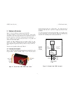
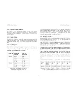
Figure 3-1 shows the hardware configuration of the MDCS2.
The imager module has a lens holder for a C/CS mount lens. There is an IR
curoff filter, with a knee at approximately 700 nm, permanently mounted
inside the lens holder. See Section 5 for appropriate lens characteristics.
There is a IEEE 1394 port on the left side of the device. The IEEE 1394
cable carries the data and signals.
Typically, the cable is plugged into the host computer IEEE 1394 card.
Power for the MDCS2 is supplied from the card, or through a separate
power supply that plugs into an IEEE 1394 hub or PC Card (7-16 VDC at >
1W).
There are no user-settable switches on the MDCS2.
3.1 Hardware
Schematic
Figure 3-2 shows the design of the internal hardware of the MDCS2. In the
imager module, a Micron MT9M001 imager of size 1280x1024 pixels
digitizes incoming light into a digital stream. The imager operates in
progressive mode only, that is, each line is output in succession from the
full frame.
The video stream has a maximum rate of 400 Mbps; the whole IEEE 1394
bus runs at 400 Mbps. Two or more MDCS2s may operate simultaneously
and send video, depending on the resolution and frame rate.
Figure 3-1. Physical layout of the MDCS2 video camera.
Imager
1394
Interface
Electronics
8, 12, or 16
bit pixels
12 MHz max
1394 Digital
Cable
1394
imaging
commands
Digital
Video
Stream
1394
commands
DCAM
Digital
Camera
Figure 3-2 Schematic of the MDCS2 electronics.
C/CS mount
for lens
IEEE 1394
port on
back of
device


