background image


Operator

’s Manual Victory WC-8H 

- Page 23 of 64 - 

Version 2.0 

4.1


Assembly Info: 


The machine comes from the factory in a shipping configuration. 


If the chip deflector or any guards are removed for shipping, replace them properly before 
operation. 


The PTO shaft is packed in the bottom of the package. 


IMPORTANT

 - Make sure that the size of the PTO shaft is correct. When mounting, keep the 

woodchipper as close to the tractor as possible. 


Always keep the PTO shaft as straight as possible. Your PTO shaft will be more efficient and 
have a longer life if you use it straightforwardly. An angle smaller than 25 degrees is 
acceptable. 


Before starting, clear the area of bystanders, especially children, and animals. 


Ensure sufficient clearance to access the machine from all sides during assembling. 


Cut the tie-down straps. 


Lay-out components next to the machine. 


Use a forklift to raise and lift the frame. Alternatively, attach a lifting device to the lifting 
bracket on top of the frame. Remove the pallet and place the machine frame on level ground. 


You can adjust the four legs to level the frame. 


Check the PTO drive shaft. Check that the shaft telescopes easily and that the shield rotates 
freely. 

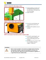
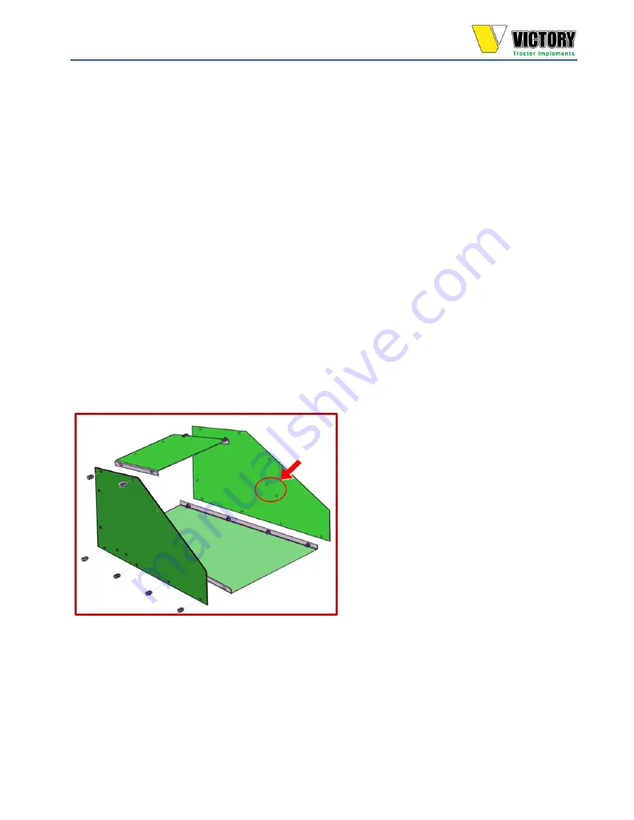
STEP 1: Assemble the Woodchipper Chute extension 


Screw the four plates of the chipper 
chute extension together, as shown in 
the figure. Mount and tighten twelve 
M10 bolts, washers, spring washers, 
and nuts. 

 
Note: 


Take note of the mounting holes for 
the hydraulic valve later.  


Summary of Contents for WC-8H

Page 1: ...Operator s Manual WC 8H WOODCHIPPER With Self Propelled Hydraulic Infeed Motor VERSION 2 0 EN 2022 ...

Page 2: ...ctorimplements com E mail address sales etractorimplements com Phone 562 534 8182 Manual info These are the original instructions The English language is binding No part of this documentation may be reproduced in any form without the written permission of Victory Tractor Implements History of changes Operator s Manual Version Date Chapters Description V1 0 2021 First edition V2 0 July 2022 All Edi...

Page 3: ...tended Operating Conditions 10 2 10 Tools Parts and Accessories for assembling and adjusting 10 3 SAFETY INFORMATION 11 3 1 Introduction 11 3 2 Generally Applicable Safety Rules 11 3 3 Personal Protective Equipment 12 3 4 General Safety Rules for Machines 12 3 5 ADDITIONAL SAFETY RULES FOR WOODCHIPPERS 13 3 6 More Safety Tips for Safe Operation 14 3 6 1 Use Safety Lights and Devices 15 3 6 2 Trans...

Page 4: ...tion checklist 31 4 4 1 Adjusting the Discharge Chute 32 4 5 Running in the woodchipper 32 4 6 Instructions before starting the Woodchipper 33 5 OPERATION 36 5 1 1 Human 36 5 1 2 Operator 36 5 1 3 Workplace 37 5 2 Preparation before operating 37 5 2 1 Using the Safety Handle 38 5 3 Operating the WC 8H 38 6 Other activities 40 7 MAINTENANCE AND REPAIR 44 7 1 LUBRICATION 45 7 2 Bearing Lubrication G...

Page 5: ...ioning and Environment 50 8 2 1 Decommissioning Requirements 50 8 2 2 Environment 51 9 EXPLODED VIEW DRAWINGS 52 9 1 Torque Specifications 60 10 FLYWHEEL KNIFE CARE 61 10 1 How long will my Woodchipper Knives last 61 11 VICTORY TRACTOR IMPLEMENTS WARRANTY 62 12 SPECIFICATIONS FEATURES PERFORMANCE 63 ...

Page 6: ... series New Holland Massy Ferguson GC series Mahindra Max series and more The Victory WC 8H series woodchipper is compact yet built to withstand commercial use Using two powerful hydraulic infeed motors the PTO propelled hydraulically powered infeed rollers grab and pull material into the chipper head The hydraulic system is powered by a belt driven hydraulic pump in the woodchipper 1 2 CE Type Pl...

Page 7: ...lements com or call 562 534 8182 to speak to one of our representatives Owner Assistance If customer service or spare parts are required please contact Victory Tractor Implements at 562 534 8182 Victory has trained technicians spare parts and equipment to service the device The parts on your machine are specially designed replace these parts always with genuine Victory parts Please reference your ...

Page 8: ... manual safety is a priority You will become aware of the dangers and hazards of operating this machine by reading it 2 2 Manual Update Reason for raising the Operator s manual to version 2 0 Editorial update according to Standard IEC 82079 Graphics and layout improved 2 3 Explanation Documentation Chapter 3 Introduction and Chapter 4 Safety is essential for anyone working on the machine For opera...

Page 9: ...tions WARNING This symbol indicates a potentially hazardous situation that if not avoided could result in death or severe injury or machine damage This ORANGE symbol indicates All WARNING notifications CAUTION This symbol indicates a potentially hazardous situation that if not avoided may result in minor or moderate injury This YELLOW symbol indicates All CAUTION notifications NOTICE This Notice s...

Page 10: ...tended use 2 9 Intended Operating Conditions Ambient temperature 0 to 40 C Temp transport Storage 10 up to 40 C Lighting Normal ambient lighting 2 10 Tools Parts and Accessories for assembling and adjusting Adjustable wrench 1 max 18 mm socket 17 mm socket 6 mm Allen key bit socket Torque wrench Awl Pick New knife nuts M10 with Nylon lock PTO Shear bolts Tape measure Feeler gauge 1 5 mm Accessorie...

Page 11: ... instructions Other activities such as service and maintenance This distinction is because operators must meet other safety requirements than the technical service staff The operator performs the daily cleaning and maintenance work described in the operating instructions 3 2 Generally Applicable Safety Rules This list contains general safety measures which must be complied with for personal safety...

Page 12: ...nsure the work area around the equipment is smooth clean and free from any obstacles Keep in mind that a dangerous situation can always arise Always wear safety glasses and protective shoes when carrying out the operation Long hair is not allowed Never wear loose or torn clothing Permanently remove jewelry When lifting heavy parts use a hoist or ask for help to prevent personal injury Ensure that ...

Page 13: ...5 ADDITIONAL SAFETY RULES FOR WOODCHIPPERS Keep the implement clear of debris and other accumulations The operator should be familiar with all functions of the device Start the implement from the driver s seat only Persons under 16 should NEVER operate or be near the woodchipper during operation Set up your work site so you are not endangering traffic and the public Take great care to provide adeq...

Page 14: ... the woodchipper or machine damage may occur When feeding wood into the machine do not allow metal bottles cans or other foreign material Do not allow processed material to build up in the discharge area It may prevent proper discharge and kick off material through the feed opening Shut off the woodchipper immediately if it becomes clogged the cutting mechanism strikes any foreign object or the ma...

Page 15: ...ol of steering and stopping Rough terrain requires a slower speed Traveling excessively on uneven terrain that causes violent shaking or bouncing will damage the attachment point on the implement and or the tractor This type of damage is not covered under warranty Use the following maximum speed for paved surfaces only 20 mph when weight is less than or equal to the weight of the tractor 10 mph wh...

Page 16: ... and recycled by specialized companies Use a piece of paper or cardboard not body parts to check for suspected leaks Wear protective gloves and safety glasses or goggles when working with hydraulic systems If an accident occurs see a doctor immediately Always treat any fluid injected into the skin within a few hours 3 8 INFEED ROLLERS SAFETY The infeed rollers can cause severe injury or death Keep...

Page 17: ...cify and test the proper size joints and telescoping members based on the power required by the implement rotation speed joint angles shock loads and expected lifetime Test the hitch geometry to prevent the driveline from Extending beyond the recommended maximum length Bottoming out Reaching a position that allows universal joints to lock Exceeding the maximum allowable angle for the constant velo...

Page 18: ...he machine Provide instructions for proper maintenance and repair Provide labels on the unit to advise the user of proper hitch dimensions and maximum safe operating speed Check that proper danger labels are supplied with the driveline concerning these parameters may be found in all driveline manufacturer s catalogs The operator s manual provides instructions for proper driveline operation mainten...

Page 19: ...chipper activities 3 11 Safety Decals and Markings on the WC 8H Your woodchipper comes equipped with all safety decals in place The decals are designed to help you safely operate your implement Read and follow their directions Read and follow instructions on all safety decals Keep all safety decals clean and legible Replace all damaged or missing decals or labels To order new ones call Victory Tra...

Page 20: ...ersion 2 0 DANGER decal DO NOT STAND BEHIND THE TRACTOR OR IMPLEMENT DANGER decal TURNING COMPONENTS Danger of being caught by rotating parts WARNING decal WARNING FOR HIGH PRESSURE HYDRAULIC FLUID WARNING decal MAX OPERATING PTO SHAFT SPEED 540 rpm ...

Page 21: ...OUT OF THE HOPPER DANGER decal on PTO Shaft ROTATING DRIVELINE HAZARD ATTENTION POINT Decal Ad grease regularly to the desired nipple 3 12 Calamities Calamities are unintended or unexpected events related to an activity s quality These events have severe harmful consequences up to and including death This includes any accident that directly or indirectly results in device damage and personal injur...

Page 22: ...Width 44 Depth 33 5 Height 53 You must set up your woodchipper before installation Please follow the steps on the following pages for a smooth 30 minute setup assembly NOTICE Before shipping the woodchipper to you the following service is done in our warehouse Bearings are greased knives are installed adjusted and the bolts are torqued according to specifications WARNING Read and understand all as...

Page 23: ...ore starting clear the area of bystanders especially children and animals Ensure sufficient clearance to access the machine from all sides during assembling Cut the tie down straps Lay out components next to the machine Use a forklift to raise and lift the frame Alternatively attach a lifting device to the lifting bracket on top of the frame Remove the pallet and place the machine frame on level g...

Page 24: ...ashers and nuts STEP 3 Mount the support leg bracket Position the support leg bracket in place and fit two bolts M10x30 including washers spring washers and nuts Tighten the nuts Insert the support leg Fix the leg in the correct position with the eye bolt STEP 4 Mount the Infeed roller lifting bar Place the Infeed roller lifting bar 1 on top of the chipper chute Fix it with four M10x30 bolts 2 wit...

Page 25: ...raulic valve Insert two bolts M8x to mount the hydraulic valve Tighten the bolts with washers and nuts STEP 7 Mount the Infeed Control handle Position the Infeed control handle 1 and fix the pivot points with two M10x bolts Use washers and nuts with Nylon locks Do not tighten completely Position the hydraulic valve control lever 2 in place and fix it with a M10x bolt washer and nut with a Nylon lo...

Page 26: ...nsure the PTO protection cover is installed STEP 10 Connect the device to the 3 point hitch Connect the woodchipper to your tractor using the 3 point hitch Secure all connecting points with Linchpins Or if you have one you can connect the woodchipper using your category 1 Quick hitch WARNING Ensure all nuts and bolts on the machine are tightened after finishing the assembly and before using the wo...

Page 27: ...ween both locking pins Calculate distance C and do the following to shorten the PTO shaft Use a hacksaw to cut distance C from both ends Cut C from both the plastic cover tubes and from the metal cores Use a file to remove all burrs from the cut edges Assemble the two ends use grease Make sure the shaft can telescope freely before installing Check the PTO Shaft s minimum overlap Always ensure the ...

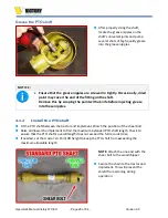
Page 28: ...nife before injecting grease into these nipples 4 1 2 Install the PTO shaft Fit the PTO shaft between the tractor and implement Watch the position of the shear bolt Raise and lower the implement to find the maximum extended PTO shaft length Check to ensure that the PTO shaft s overall length does not exceed the full recorded size If needed set the tractor s 3 Point lift height to keep the PTO shaf...

Page 29: ...out of the way Slowly increase the engine speed of your tractor until the PTO speed reaches 540 rpm Usually a mark on your tractor s tachometer will indicate the necessary engine speed to achieve the required PTO speed Please remember to run the woodchipper at the proper 540 rpm PTO speed regardless of the size of the material you are chipping Reduced PTO speed can cause plugging of the discharge ...

Page 30: ...oth and free of obstacles Always maintain a full view of the working area during operation Keep animals and children far away from the device Purge any air from the hydraulic system Locate the flow control valve Push the lever forward to 10 this is fully open and will allow the oil to flow easily through the valve Use this lever to increase or decrease the speed of the infeed roller 10 is the fast...

Page 31: ...the manual provided with the tractor 4 4 Pre operation checklist A pre operation checklist is provided for the operator It is essential for both personal safety and maintaining an excellent mechanical condition that this checklist is followed Before operating the Woodchipper and each time after that check off the following areas 1 Ensure the hydraulic oil level is correct Fill the oil reservoir wi...

Page 32: ...ng mechanical items After operating for 1 hour 1 Torque all fasteners 2 Check the condition of flywheel bearings 3 Check the condition and clearance of the twig breaker and the clearance between flywheel knives and stationary counter knife Adjust or replace as required 4 Check for entangled material Remove all entangled material before resuming work 5 Lubricate all grease nipples After operating f...

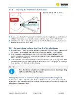
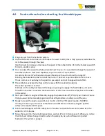
Page 33: ...ithout effort The safety bar activates the flow control valve with three detent positions The center position is neutral Pull back on the safety bar toward the hopper opening to engage the feed rollers and push forward on the lever to reverse the feed rollers At this time move the safety bar to the valve in the center Start your tractor s engine While idle engage the power take off PTO of your tra...

Page 34: ...ts and loose hose fittings at this time Some hydraulic fittings are left slightly open for shipping purposes It is important to remember to adjust the speed of the infeed roller when you start working Start with the lowest rate first 1 and then increase the speed incrementally until you find the best speed for the material you are running and the hp of your tractor Once you have found the proper i...

Page 35: ...Operator s Manual Victory WC 8H Page 35 of 64 Version 2 0 ...

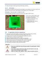
Page 36: ...woodchipper for anything other than what it is meant for DO NOT operate the woodchipper unless all safety guards and protection plates are in place DO NOT leave the machine unattended while it is running CAUTION Keep your hands away from all moving components Rotating parts can cause severe injury Don t stand too close to the WC 8H A safe distance is approx 1 m No other persons are allowed around ...

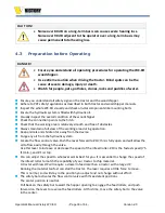
Page 37: ...ating Inspect the whole WC 8H visually and check all vital components like hoses and their connections lines hoses and wires for damage kinking wear or dirt Visually inspect the condition of the engine and hydraulic pump system Check the hydraulic oil level Add oil if needed Replace the hydraulic oil when the oil is dirty or contaminated Check the PTO Shaft s Interference as described in the previ...

Page 38: ...e than 25 degrees from the centerline The chipper must rest on solid level ground before operating DO NOT operate while raised by the three point hitch Start the chipper slowly idle with the PTO engaged Gradually increase engine RPM until the tractor PTO speed is 540 rpm not 540 engine rpm The woodchipper running speed is 540 RPM Lower RPM can damage the woodchipper if material jams and stops the ...

Page 39: ...g of the discharge chute rough cutting with more vibration than usual feed roller shaft broken the main bearing house broken the main bearing working loose and the flywheel or knives hitting the case or bed knife feed roller not feeding The best way to tell if the knives need sharpening is to watch the chips coming out of the chip discharge If they are long and straight the knife blades require se...

Page 40: ...he other side Adjust or replace the drive belts Remove the pulley cover Untighten bolts 1 x4 Use adjusting bolts 4 to move the lower bearing bracket 2 up or down to untighten replace or tighten the drive belts Adjust the drive belt s tension according to the following figure Tighten all bolts 1 80 feet pounds Secure the adjusting bolts Mount the pulley cover NOTE Always keep the power input shaft ...

Page 41: ...drive belt Remove the pulley cover Untighten adjusting bolt 2 Untighten oil pump mounting bolts 1 Move the oil pump to the left or right to tighten or untighten the drive belt Adjust the drive belt as shown in the previous figure Tighten mounting bolts 1 Secure adjusting bolt 2 Mount the pulley cover ...

Page 42: ... thoroughly to ensure the Allen key bit socket fits appropriately If not you may strip the heads out Air blow guns are also helpful Insert a 6 mm Allen socket wrench and a 17 mm socket wrench at the backside to remove the four knife bolts Remove the knife Be careful not to drop the fasteners into the flywheel chamber Clean the knife blade recess surface properly Place a new knife Mount and hand ti...

Page 43: ...can pass through the chipper without shearing if the distance is too large This can cause the discharge chute to plug Rotate the flywheel by hand for two or three revolutions to ensure no interference issues Re attach the PTO shaft Filling the Hydraulic tank Remove the oil filler cap Use a funnel to add oil if necessary Check the oil level Changing the Oil Filter Remove the hydraulic line from the...

Page 44: ...in an enclosure Always perform maintenance on a level and solid surface Only trained specialists with education and knowledge of the machine and safety procedures are entitled to maintenance or service work Always strictly adhered to service intervals prescribed by the manufacturer Always follow the maintenance schedule given in the Operator s manual closely Failure to do so may result in machine ...

Page 45: ...rfill bearings Overfill can lead to excessive and or unseating of seals Inject grease in small increments and under light pressure Whenever possible rotate the bearings while adding grease to ensure equal distribution throughout the raceways Bearings in extreme environments will require more frequent greasing intervals 7 2 Bearing Lubrication Guide Based on Environmental Conditions There are many ...

Page 46: ...nment grease the bearings at 500 hour intervals PTO Shaft Grease the two grease nipples on the universal joints every 10 hours using high quality multi purpose grease 7 3 Hydraulic oil reservoir Fill the oil reservoir with 8 gallons of 46HM Hydraulic oil Using the specified oil will give you the most extended life and the best performance for this machine The hydraulic system is a low pressure low...

Page 47: ...as broken Replace shear bolt from PTO shaft Disk stalls or stops Obstructed discharge Plugged flywheel Use a branch or similar object to clean the chute Clean the flywheel housing Low infeed power Dull knife blades Obstructed discharge Improper blade clearance Renew the knives Clear the discharge chute Adjust clearance between knives and counter knife Feed rollers stop unexpectedly Hydraulic oil l...

Page 48: ...ed viscosity oil The flywheel will not turn properly Obstruction in the discharge chute Low drive belt tension Clean the discharge chute Adjust or replace the drive belts 7 6 SPARE PARTS AND WEARING PARTS Any mechanical installation is always subject to wear and tear Keeping a limited number of crucial parts in stock is advisable to avoid costly downtime The installation mainly includes unique and...

Page 49: ...onomically and technically challenging to repair Often these are universal purchase parts such as knives bearings bushings etc For the reliable operation of a tool it is essential that wearing parts are of high quality It is also helpful that a service organization responds to failure situations and unexpected material needs Wear parts are permanently excluded from the warranty Wearing parts for t...

Page 50: ...lace if necessary Repaint parts where paint is worn or scratched to prevent rust Turn the feed hopper up and lock it It is best to store the machine inside If that is not possible securely cover with a waterproof tarp and tie down Clean off any dirt or dust accumulated on the woodchipper and any moving parts and protect it against corrosion by lightly oiling it Store in an area away from human act...

Page 51: ...sposed of as chemical waste in the European Union So do not dispose of these products with regular commercial waste To prevent potential harm to the environment or human health from uncontrolled waste disposal please submit the products to a separate waste management organization and promote the sustainable reuse of materials Information on different waste collection is available from your municip...

Page 52: ...2 0 9 EXPLODED VIEW DRAWINGS VICTORY WC 8H Exploded View Main Parts Main Parts Pos Part number Description Qty 1 Frame 1 2 Frame mounting plate 1 3 Flywheel housing 2 4 Flywheel housing top 1 5 Bolt x 6 Washer x 7 Discharge chute 1 8 Nut x 9 Washer 10 Bolt ...

Page 53: ...oded View Flywheel with Knifes Parts Flywheel with knives Pos Part number Description Qty 1 Flywheel 2 Chipper Knife blade 2 3 Bolt M10x1 5x35 Flat socket cap screw GR 10 9 8 4 Bolt M x 5 Nut Nylon lock 6 Flywheel shaft Key 7 Flywheel shaft 8 Nut M10x1 5 Nylon lock 9 Washer M10 ...

Page 54: ...Exploded View Hydraulic Infeed System Parts Infeed System Pos Part number Description Qty 1 Frame mounting plate 1 2 Nut x 3 Bolt 4 Bearing block 2 5 Cover shell 6 Nut M10x1 5 Nylon lock 7 Bolt M10x1 5x35 Flat socket cap screw GR 10 9 3 8 Bed Counter knife 1 9 Bearing block ...

Page 55: ...her 18 Nut 19 Bolt 20 Infeed roller shaft 21 Control handle bracket 22 Hydraulic motor 23 Nut 24 Infeed bracket spring 25 Infeed control handle 26 Infeed Chute extension 27 Nut 28 Spring washer 29 Washer 30 Connection plate 4 31 Collar ring 32 Split pin 33 Bolt M10x30 8 34 Infeed roller bearing block 2 35 Cover shell 36 Bolt M10x 37 Spring washer M10 38 Washer M10 ...

Page 56: ...ew Drive System Parts Drive System Pos Part number Description Qty 1 Lower frame 1 2 Upper frame 1 3 Bolt M x 4 4 Nut M 2 5 Bolt M x 2 6 Wing nut M 2 7 Spring washer M 4 8 Washer M 8 9 Bolt M x 8 10 Bearing block 1 11 Nut M x 8 12 Bolt M x 8 13 Flywheel 1 14 Cover plate 1 15 Washer M ...

Page 57: ...wheel pulley 1 23 Bolt M x 1 24 Pulley cover 1 25 Main drive pulley 1 26 Pulley clamping bush fastener power input shaft 4 27 Pulley clamping bush fastener power input shaft 4 28 Main drive Pulley clamping bush 1 29 Drive Belt 4 30 Bolt M x 4 31 Power input shaft bearing block 2 32 Washer 4 33 Nut M 4 34 Drive belt Hydraulic pump 1 35 Drive belts adjusting bolt 4 36 Adjustable hitch pin bracket 2 ...

Page 58: ...H Exploded View Flywheel Bearings Parts Flywheel bearings Pos Part number Description Qty 1 Power input shaft bearing block bracket 1 2 Nut 4 3 Power input shaft bearing block 2 4 Bolt 4 5 Washer 8 6 Spring washer 4 7 Nut 4 8 Power input shaft 1 9 Power input shaft key 1 ...

Page 59: ...iew Infeed Hopper Hydraulic valve Parts Infeed Hopper Hydraulic valve Pos Part number Description Qty 1 Bottom plate 1 2 Side plates set 1 3 Nut 12 4 Securing ring 12 5 Support bracket 1 6 Eyebolt 1 7 Support 1 8 Handle bracket 1 9 Bolt 1 10 Top plate 1 11 Bolt 1 12 Hydraulic valve 1 ...

Page 60: ...er 16 20 Nut 2 21 Bolt 10 22 Nut Nylon lock 12 9 1 Torque Specifications The table below gives the correct torque values for various bolts nuts and cap screws Tighten all bolts to the torques specified unless otherwise noted Check the tightness of bolts periodically using this bolt torque chart as a guide Replace fasteners with the same length and grade of bolt ...

Page 61: ...lthough they are made of high quality steel they are not indestructible All chippers will perform better when chipping fresh green clean limbs The moisture in the limbs lubricates the knives and reduces friction Do not attempt to chip rotten wood it will plug your woodchipper You can chip dry material this will wear the knives faster than fresh green material Use your best judgment on this type of...

Page 62: ...vels grease points and driveline shafts Claims under this Warranty should be made directly to Victory Tractor Implements and all warranty adjustments must be made through an authorized Victory dealer Victory reserves the right to make changes in materials or design of the product at any time without notice This Warranty shall not be interpreted to render Victory liable for damages of any kind dire...

Page 63: ...l tank 8 Gallons Hydraulic oil type 46HM Infeed functions Stop Reverse Forward Hydraulic Pump 3 6 G pm Safety Stop Bar Yes with a Reverse function Variable Speed Control Yes Nylon Wrapp protected Hoses Yes Discharge Chute Rotation 360 Degrees Flywheel Housing Material 6 mm PTO Shaft included with Shear pin Paint Powder coated Colors body Chute Green Yellow Crate Dimensions 44 x 33 5 x 53 Shipping ...

Page 64: ...reliable and professional wood chipping without concerns The compact WC 8H is suitable for your small to mid sized tractors between 25 to 45 hp utilizing your CAT I II 3 Point Hitch High quality hydraulic motors power the infeed rollers avoiding wood jams by switching direction and speed Victory s WC 8H machine complies with all safety standards and is CE tested following the 2006 42 EC machine di...

Reviews: