Victory participates in the KCL CADalog, the most current source of CAD symbols for foodservice designers worldwide. Symbols include
standard equipment in plan, side, front and 3-D views, layered for FEDA/FCSI recommended guidelines.
Continuous product development may necessitate specification changes and design without notice.
Victory Refrigeration, Inc.
Warming Cabinets
CHARACTERISTICS
ONE SECTION
TWO SECTION
Reach-In
Pass-Thru
Reach-In
Pass-Thru
Width, Overall
26
1
/
2
26
1
/
2
52
1
/
8
52
1
/
8
Depth, Overall (incl. handles)
35
7
/
8
39
3
/
8
35
7
/
8
39
3
/
8
Height, Overall (incl. adj. legs)
84
84
84
84
Depth, Doors Open 90º
58
1
/
2
84
5
/
8
65
1
/
4
98
1
/
8
Clear Door Width
21
1
/
8
21
1
/
8
21
1
/
8
21
1
/
8
Clear Full Door Height
55
1
/
4
55
1
/
4
55
1
/
4
55
1
/
4
Clear Half Door Height
25
3
/
8
25
3
/
8
25
3
/
8
25
3
/
8
Capacity Net (cubic feet)
21.5
23.7
46.5
48.0
No. of Full Doors
1
2
2
4
No. of Half Doors
2
4
4
8
No. of Shelves
3
3
6
6
Shelf Area (square feet)
17.1
17.1
36.0
36.0
Cabinet Voltage
208-240/60/1 208-240/60/1 208-240/60/1 208-240/60/1
Max. Fuse Size T.D.
15 Amps
15 Amps
20 Amps
20 Amps
Feed Wires
3
3
3
3
Heater Watts per Section (@240V)
1500
1500
1500
1500
Total Wattage (Heaters & Fan @240V)
1500
1500
3000
3000
Total Amperes
6.3
6.3
13.0
13.0
Crated dim. & wts.
Ht. Width Depth Cu.Ft. S SA A
One Section
81
1
/
2
36
1
/
2
43
82.2 330 325 310
Two Section
81
1
/
2
63
43 143.3 560 550 540
Approximate Pass-Thru weights, add 15%
Dimensional tolerance ±
1
/
4
” Metric dimensions (MM)
Copyright January 2004
Printed in U.S.A. 010413
PART OF
AGA
FOODSERVICE GROUP
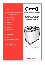
39.38
(1000)
22.50
(571)
16.38
(415)
13.25
(336)
35.88
(911)
34.38
(873)
32.38
(822)
84.00
(2133)
26.50
(673)
6.00(152)
55.25
(1403)
21.12
(536)
14.12
(358)
HUMIDITY VENT
ELEC.
CONN.
ELEC.
CONN.
PASS-THRU MODELS
REACH-IN MODELS
39.38
(1000)
48.12
(1222)
25.63
(651)
13.25
(336)
16.38
(415)
35.88
(911)
84.00
(2133)
52.12
(1323)
55.25
(1403)
21.12
(536)
21.12
(536)
14.12
(358)
HUMIDITY VENTS
ELEC.
CONN.
ELEC.
CONN.
6.00(152)
NOTE:
If cabinet is located directly against
wall and/or under low ceiling, a minimum
clearance of 2” is required.
We reserve the right to change
specifications and product design
without notice. Such revisions do not
entitle the buyer to corresponding
changes, improvements, additions or
replacements for previously purchased
equipment.