


ESS3/ESS4
- 9 -
SECTION 1
centers itself in a recessed pocket in the top of the Body.
Don’t forget the Thrust
Washer!
Regulator function will be impaired without it.
18. Install the Bonnet
[2]
onto the Body. Take care while slipping the Bonnet down over the
internal components – the ribs inside the Bonnet must slide into the scallops of the Guide
Bushing.
TIP: If your Bonnet still has the Gas I.D. decal on it, make sure you get the Bonnet
oriented correctly with the Gas I.D. decal facing front.
19. Install the five (for ESS3) or six (for ESS4) Socket Head Cap Screws
[10]
into the
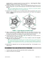
Bonnet. Tighten all bolts until snug, then torque each to 12-15 ft-lbs in the sequence
shown in
FIGURE 1
.
FIGURE 1 - Torque Sequence for Bonnet Screws
20. Apply a small amount of CHRISTO-LUBE® #129 to the top surface of the Bonnet (the
surface around the square of the Drive Screw), then slip the Knob
[9]
into position – with
the square hole inside the knob mating to the square shaft of the Drive Screw.
21. Install the #10-32 Screw
[7]
, Lock Washer
[8A]
and Washer
[8]
to hold the Knob on.
Torque this Screw a minimum of 30 in-lbs.
22. Apply new Knob or Gas I.D. decals
[6, 30, 31]
as needed to insure the Regulator
maintains clear visual identification.
TIP: If you’re replacing the rear Body Gas I.D. decal, make sure you don’t cover up
the model number stamped on the Body. The Gas I.D. decal should be positioned
right next to the stamping, with the arrow on the decal pointing to the stamped model
number.
23. Disconnect the Regulator from the Inlet Swivel Assembly Plug. The Regulator is now
ready to test.
RECOMMENDED TOOLS AND SUPPLIES FOR TEST PROCEDURES
•
Test Gun (quick opening on/off valve) with #52 (.0635”) restricting orifice
•
Source of oil-free air or dry nitrogen


