


5
04/06/04 LIT-H200X-E02 H200.doc
SET POINT
50%
db
OUTPUT #1
d2
HUMIDIFICATION
35%
30%
45%
40%
pb
0%
HUMIDIFICATION
100%
OUTPUT #2
100%
0%
d2
OUTPUT #1
DEHUMIDIFICATION
65%
55%
60%
0%
70%
DEHUMIDIFICATION
100%
0%
100%
OUTPUT #2
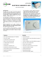
CONTROL SCHEMATIC:
TABLE 3: H200 PARAMETERS
CODE
VALUES
DEFAULT
VALUE
DESCRIPTION
Db
0 to 40 % R.H.
25% R.H.
Dead Band between humidification and dehumidification.
SL
30 to 100 % R.H.
85% R.H.
Supply Limitation: High humidity limit in the supply duct (H270 only)
d2
0 to 199 % (of proportional
band)
100%
Differential for output #2": Shift for output 2 relative to output 1
Pb
0 = 1.6 % R.H.
1 = 3.2 % R.H.
2 = 6.4 % R.H.
3 = 12.8 % R.H.
4 = 25.6 % R.H.
2= 6.4%
R.H.
Proportional Band
o1
0 = Humidification
1 = Dehumidification
"Output #1" Action for output no 1
o2
0 = Humidification
1 = Dehumidification
"Output #2" Action for output no 2
cc
2 = Without integral
3 = With integral
3
"Control Code"
t1
0 = On/off
1 = 8 minutes
2 = 1 second
"Time #1" Time period for output no 1
t2
0 = On/off
1 = 8 minutes
2 = 1 second
"Time #2" Time period for output no. 2
rA
0 = °C
1 = °F
1 DO NOT
CHANGE
"Range" Temperature Scale
Ca
±
13 %
Calibration ( deviation mode: DO NOT MODIFY: USE AUTOCAL PROCEDURE;
FOR H100 TRANSMITTER, USE THE ZERO POTENTIOMETER ON THE
TRANSMITTER.
hA
0 à 127
"Hardware assembly" Code related to thermostat model and entered at initial setup at
the factory.
it
1 to 99 = 1 TO 99 MINUTES
60
"Integral time" Error integration time.
Lt
-40 à +40 °C (-40 à 105 °F)
-20 °F
"Lower temperature" minimum outside temperature for setpoint reset (model H270 only)
Ht
-40 à +40 °C (-40 à 105 °F)
32 °F
"Higher temperature" maximum outside temperature for setpoint reset (model H270
only)
rE
1 à 99 % R.H.
20 % R.H.
"Reset” Minimum humidity value ( % HR ) (model H270 only)
Example: rE = 20%. Humidity setpoint will be reset from selected setpoint to 20%, from
Ht to Lt
pb = proportionnal band
d2 = differential between output #1 and #2
db = dead band between humidification
and dehumidification
Fig.7: Control schematic


