background image


Compact,


Multipurpose 


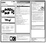
Ultrasonic Humidifier 


series 


F25

F245


F25UV

F245UV 


INSTALLATION AND 

OPERATION MANUAL


Thank you for purchasing this UCAN ultrasonic humidifier unit. 

Please read these instructions thoroughly for correct installation, 

Maintenance and inspection of the unit. 


Keep Handy For Quick Reference 


UCAN Co., Ltd. 


5-6-19 Sanda-cho, Hachioji-city, Tokyo 193-0832, Japan 

Tel: +81-42-665-8846 Fax: +81-42-661-3887 

URL        http://www.ucan.co.jp/eng/ 

E-mail


[email protected] 

Sales Offices: Tokyo, Osaka, Nagoya, Fukuoka and Sendai 


Summary of Contents for FT-F Series

Page 1: ...idifier unit Please read these instructions thoroughly for correct installation Maintenance and inspection of the unit Keep Handy For Quick Reference UCAN Co Ltd 5 6 19 Sanda cho Hachioji city Tokyo 1...

Page 2: ...ower Do not touch any electric circuit during power on especially by wet hands It will get electric shock All of electric cable wire should not damage processing pulling or forcibly bending It will ca...

Page 3: ...s lower then freezing point all of water pipe lines should be protected from freezing Otherwise pipes may brake due to the freezing The life of the oscillator is about 5 000 hours The life sometimes b...

Page 4: ...u use extension cable for the box be sure to use proper cable 3 The location of the box should be considered about maintenance such as easy removable of the front cover 1 3 Installation of Humidistat...

Page 5: ...drain pan should not be twisted and set it in slant for water flow Drain pan Hunging type Hunging bolt by customer Humidifier unit Wall mounting bracket Drain pan Humidifier unit Wall mounting type 10...

Page 6: ...ow out to drainage pipe or drain pan The hose should be set on the slant 6 Leave the black cap intact on the drainage outlet The cap to be removed only for draining water reservoir to do cleaning or m...

Page 7: ...t waterless operation will make stop the operation of the unit However the water supply solenoid valve has still been opened until shut off the power switch of the unit If switch off the unit the sole...

Page 8: ...spray nozzle with both hands then lift up the right side of the top cover 3 Pull out the top cover toward the upper right side Condensation formed on the nozzles Please take care not to spill it CAUTI...

Page 9: ...val method of the fan box Replacement of the oscillators the float sensors or maintenance of the water supply solenoid valve Procedure 1 Unlock the snap lock on both side of the fan box 2 Slide the fa...

Page 10: ...cation 4 Pull out the bottom cover toward the front side F125 F245 loosen the fixing screws on the bottom side of the bottom cover about twice in advance After that it becomes possible to replace the...

Page 11: ...is not necessary to remove the nuts 2 Slide the PCB with bracket as shown above Remove the connectors if necessary Replacement method of UV lamp 1 Loosen the M4 screws that fixing the both ends of th...

Page 12: ...bout twice in advance 3 Pull out the UV lamp Please be careful packing is not twisted or out when replace the UV lamp View from the bottom side UV lamp View from back side FT F125 F245 The back cover...

Page 13: ...filter 2 Remove the air filter as shown below The method of the cleaning of the air filter Clean up any built up of the dust by hand or blow off by compressed air In case of heavy contamination wash t...

Page 14: ...up the stem and the float carefully 2 Remove the stopper and pull out the float for the above 3 When taking out the float be sure to see which end is up It must be reassembled in the right direction T...

Page 15: ...ner must be set between the water line and the water inlet pipe to protect the unit by eliminating the dirt or the dust 1 Close the water supply valve 2 Turn the knob of the strainer holder counter cl...

Page 16: ...source switch before checking 1 Remove the transformer cover 2 Check the fuse If it burn out replace the spare one fastened to the switch base with the tape 3 Turn on the switch of the main electric...

Page 17: ...ectric surge occurred by lightning strike may cause damage of PCB 5 If use megger tester to check PCB it may cause damage of the PCB 6 If the water of the tank has grits pebbles or iron powder etc and...

Page 18: ...the indication is showing under 10 ohm the transistor is OK but if it shows close to ZERO the transistor is out of order Then next step checking should be done Touch red probe PLUS at B side Base and...

Page 19: ...the duct hose Overflow Deterioration with age No slope provided Dirt caught in the solenoid valve Replace Give the hose some incline Dismantle the valve and clean 2 No spray output at all Trouble fun...

Page 20: ...UCAN s installation and operation manuals 3 If the products have been modified or altered without written agreement with UCAN 4 Under circumstances of any direct indirect incidental consequential dama...

Reviews: