

3
4
5
1
6
2
Vemer S.p.A.
I - 32032 Feltre (BL) • Via Camp Lonc, 16
Tel +39 0439 80638 • Fax +39 0439 80619
e-mail: [email protected] - web site: www.vemer.it
MKIS00916-010-EN
Mod.
HUMI
Electronic flush-mounting humidistats for humidity regulation which performs
actions of type 1B and intended for operating in environments with Pollution
Degree 2 and Overvoltage Category III (EN60730-1).
Codel
Model
Description
VE379400
Humi
Electronic flush-mounting humidistat 230V
SAFETY WARNINGS
During product installation and operation it is necessary to observe the
following instructions:
1) The device must be installed by a qualified person, in strict compliance with the
connection diagrams.
2) Do not power or connect the device if any part of it is damaged.
3) After installation, inaccessibility to the connection terminals without appropriate
tools must be guaranteed.
4) The device must be installed and activated in compliance with current electric
systems standards.
5) Before accessing the connection terminals, verify that the leads are not live.
6) In the electrical system of the building where the instrument must be installed,
a protection device from the overcurrents must be present.
TECHNICAL SPECIFICATIONS
• Power supply:
– 230Vac (-15% ÷ +10%) 50/60Hz
– absorption: 4VA (0.5W)
• Installation on 3 modules box (503 type)
• Terminals:
– 3 terminals for 1.5 mm2 cables for bistable output relay 5A / 250 Vac
– 2 terminals for 1.5 mm2 cables for power supply
• Output: bistable relay 5 (3) A / 250Vac
• Minimum time between a switching and the next one: 1 minute
• Regulation type: on/off with fixed differential of ± 2.5% RH
• Regulation range: 30% ÷ 90% RH
• 2-position selector switch: always off, automatic
• Operating humidity: 20÷90% non condensing
• Protection degree: IP40
• Insulation: reinforced among accessible parts (frontal) and all other terminals
• Mechanical locks on the knob to limit the setpoint
The humidistat signals the error probe condition by blinking the led 2 times
per second.
In this case the regulation is inhibited and the relay contact remains
between terminals 2 and 3. Contact the Technical Service.
REFERENCE STANDARDS
Compliance with Community Directives
2014/35/EU (LVD)
2014/30/EU (EMCD)
is declared with reference to the following harmonized standards:
EN 60730-1 • EN 60730-2-13
• Install the humidistat at a height of about 1.5 m above the floor, away from
direct sunlight, away from doors, windows, heat sources, locations with
excess or total lack of ventilation.
• The device is sold already mounted with
anthracite colour. To transform it in the
white version, remove the knob and the
cover, acting on the hooks placed on
the upper and lower side of the device
and mount the cover and the white knob
included in the package.
• Make the connections by respecting the
diagrams described in this manual.
• Use the selector switch to turn on or off the humidistat:
- position 0: humidistat off, no regulation
- position |: humidistat switched on, active regulation for detected
humidity values exceeding the set value
• Use the knob to set the desired
humidity level.
It’s possible to set values between
30% RH and 90% RH.
When the humidity value present
in the room exceeds the
set value, the red led lights up
and the relay switches between
contacts 1-2.
Note: In order to preserve the life of the system, the minimum time between
a relay switching and the next one is 1 minute. However, the led status
updating is immediate. Therefore, after using the regulation knob, it is
possible to find a discrepancy between what is indicated by the led and the
actual status of the relay. This condition lasts for up to 1 minute.
The device has two ring nuts to limit mechanically the range of settable
values if the humidistat is installed in public places or in hotel rooms.
To limit the range, proceed as follows:
- Set the knob in an intermediate value of the desired range
- Remove the knob.
- Under the knob there are two ring nuts marked by the word “min” and
“MAX”, respectively for the lower and upper limit.
- Turn the “min” ring nut clockwise and “MAX” anticlockwise until the
minimum value range (see the humidity values reported on the cover).
- Turn the “MAX” ring nut anticlockwise and until the maximum value
range (see the humidity values reported on the cover).
- Replace the knob, making sure that the indicator of the setpoint on the
knob is in the same position when the knob has been removed.
To remove the limitation to the setpoint and reset the range 30% ÷ 90% RH
turn the two ring nuts up to bring the locks of limitation in a position outside
the range 30% ÷ 90% RH.
• Fix the device inside the 3 modules box in compliance with the assembly diagrams
described on the back of this instruction sheet. The accessories for the installation
included in the package allow the mounting of the plates described in the diagram
“adjustable cover plates” and they are:
- A mount
- B mount (it could be necessary to remove the side cogs)
- AIR mount
- couple of side BM plastic elements (both of white colour and grey colour)
- couple of side VI plastic elements (both of white colour and grey colour)
- covers and knobs of white colour and anthracite grey colour.
The adapters inside the box allow the monitoring of the following cover plates:
For information about the possibility to adapt the humidistat with different
cover plates from those listed, contact the Technical Service.
* through mount that you can buy on request (code VE767500)
• All the above trademarks are the property of their respective owners.
ABB Chiara series
ABB Mylos series
Ave S44 series
Bticino Axolute series
Bticino Axolute Air*
Bticino Light series
Bticino Light tech series
Bticino Living series
Bticino Livinglight series
Bticino Livinglight Air series
Bticino Matix series
Gewiss Chorus series
Vimar Eikon series
Vimar Eikon Evo series
Vimar Idea series
Vimar Plana series
Vimar Arké series
10-2017
User Manual
ELECTRONIC FLUSH-MOUNTING HUMIDISTAT
Read all instructions carefully
OPERATION
PACKAGE CONTENTS
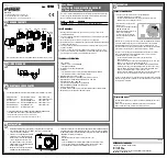
WIRING DIAGRAMS
ADJUSTABLE COVER PLATES
INSTALLATION
Cover, knob and plastic elements are available in white and anthracite grey colours
humidistat
Covers
VI plastic
elements
BM plastic
elements
A mount
B mount
Setpoint modification
Error probe signal
AIR mount
C
O
M
NO
NC
N
L
230V
~
Keo-A
1
2
3
4
5


