


XX163-11-00 Rev 1006 SVFT-PRS Pressurized Dome Housing
Installation
•
13
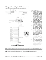
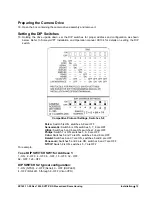
Wiring and Assembling the 23-Pin Connector
(If the discrete 23-pin connector with crimp pins was provided)
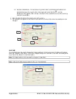
7. Assemble the 23-pin connector
as shown in Figure 8.
a. Identify the cables required
for attaching to the 23-pin
connector. There should be
a minimum of three (3),
power (18 to 32 VAC),
control (RS-422/485) and
video (RG-59 or twisted
pair cable). There could be
optional cables for alarm
inputs or the relay output
(jacketed twisted pair).
b. Route all cables through
the provided 2 in. (51 mm)
length of shrink wrap tubing
and push the tubing a few
feet down the cable bundle.
c. Route all cables through
the provided connector
strain relief fitting and push
the connector near the
shrink wrap tubing.
d. Verify that each cable has
had the jacket stripped
back. If not, strip back the
jacket and individual wire
covering to the dimensions
shown in Figure 8.
e. Identify each wire signal
and label it (A, B, C, D, etc.)
in accordance with the 23-
pin connector assembly
wires.
f. Attach a crimp connector to
each wire and fasten with
crimp tool number
M22520/1-01 and turret
number M22520/1-02
manufactured by Astro Tool
Company or equivalent.
Note: Use the provided large crimp connector for the Ground connection in the Control (RS-422/485) cable.
Note: The wire color code may not match Figure 3. Use the wire labels for absolute reference.
Figure 8
23-Pin Connector Assembly Details
Summary of Contents for SVFT-PRS22E
Page 2: ......
Page 16: ...10 Installation XX163 11 00 Rev 1006 SVFT PRS Pressurized Dome Housing...
Page 31: ......