Vicon SVFT-PRS22E Installation And Operation Manual Download Page 13

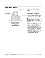
XX163-11-00 Rev 1006 SVFT-PRS Pressurized Dome Housing 

Installation  

  7 

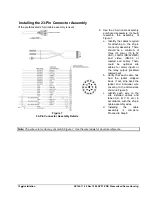
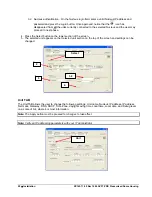
g.  Insert each labeled crimp connector into its respective labeled 23-pin connector position (A, B, C, D, 

etc.). Verify that each is firmly seated.  

h.  Pull the strain relief fitting back up the cable and screw it firmly into the base of the 23-pin connector 

assembly. 

i. 

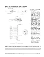
Gather all the cables at the other end of the strain relief fitting into a bundle and tighten the two (2) 
strain relief fitting screws until the cables are snugly captured. 

j. 

Pull the shrink wrap tubing back up the cable and push it over the strain relief fitting until it meets the 
base of the 23-pin connector. 

k.  Using a heat gun or other directional heat source, heat the shrink wrap tubing until it shrinks over the 

23-pin connector assembly and cables. 

l.  Identify each wire on the site installed cables and label it (A, B, C, D, etc.) in accordance with the 

labels on the 23-pin connector assembly wires. Assembling the connector is complete. 

Caution: Overheating the shrink wrap tubing can result in damage to the tubing and the entire 23-pin 

connector assembly. 

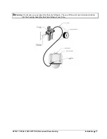
8.  Remove the service cover from the front of the wall mount by removing the four (4) captive screws. 
9.  Route the 23-pin connector assembly through the service cover and out the back of the wall mount. 

Leave the 23-pin connector assembly and an excess of about 2 in. (51 mm) of cable at the service 
opening. 

10. Inspect the top of the housing assembly and verify that there is no debris on the gasket area. If there is, 

wipe this surface clean with a cloth. 

11.  Lift the top of the housing assembly up to the wall mount’s pressurized housing mounting flange. Align the 

two (2) sets of four (4) mounting holes so that the relief valve is located closest to the service opening 
(slightly off to the right side, facing forward). Press firmly. 

Note: Failure to correctly orient the Housing can cause difficulty in future servicing. 

 
12. Insert the four (4) provided ¼-20 x 5/8 in. (16 mm) long hex head screws through the provided ¼ in. 

(6 mm) lockwashers and into the mounting holes. Tighten all screws securely with a 5/8 in. (16 mm) 
socket wrench. Carefully release the housing assembly and verify that the mount can support the weight 
load. 

13. With the housing assembly attached to the wall mount, locate the 23-pin connector assembly in the 

service opening. 

14. Insert the 23-pin connector assembly into the mating 23-pin connector on the top of the housing 

assembly. Turn it until it drops down into the keyed slot and twist it clockwise ¼ turn to lock it. 

15. Connect the previously labeled site wiring to their corresponding cable assembly labeled wires using 

standard wiring practices such as wire nuts. If using conduit, route all cables through the liquid-tight 
fitting/conduit, previously installed in the access hole, before connecting to the site wiring. 

16. At the lower side, remove the cap from the fill valve. Using a small-tipped instrument, press the internal 

pin down to release any residual gas from the housing. 

17.  Loosen the eight (8) captive screws from the trim ring/lower dome assembly and lower it. Allow the lower 

dome to hang from its safety cord during the remaining assembly. 

Summary of Contents for SVFT-PRS22E

Page 1: ...his system has not been designed to be used in life critical situations and must not be used for this purpose Copyright 2006 Vicon Industries Inc All rights reserved Product specifications subject to...

Page 2: ......

Page 3: ...the unit 13 Outdoor Cable Grounding Use only grounded outdoor cables to protect against voltage surges and static charges Section 810 of the National Electrical Code ANSI NFPA 70 1984 provides informa...

Page 4: ...an be determined by turning equipment off and on the user is encouraged to try and correct the interference by one or more of the following measures Reorient the receiving antenna Relocate the equipme...

Page 5: ...nd Assembling the 23 Pin Connector 6 Preparing the Camera Drive 8 Setting the DIP Switches 8 Pressurizing the Housing Assembly 9 Pipe Mount Method 11 Installing the Pipe Mount 11 Installing the 23 Pin...

Page 6: ...iv Quick Installation XX163 11 00 Rev 1006 SVFT PRS Pressurized Dome Housing Quick Installation Q U I C K I N S T A L L A T I O N Q U I C K I N S T A L L A T I O N...

Page 7: ...s SVFT PRS Pressurized Dome Housing Components The SVFT PRS consists of a pressurized enclosure a sealed lower dome assembly and mounting brackets for the SurveyorVFT Camera Drive In addition the hous...

Page 8: ...oor with clear lower dome coaxial output NTSC PAL SVFT PRS35 SVFT PRS35C 9103 00 9103 01 PRESSURIZED COLOR CAMERA DOME SYSTEM includes variable speed drive 35X high resolution day night camera lens ou...

Page 9: ...and clip are provided on the inside to connect the camera drive latch during installation The lower side of the housing is equipped with a fill valve Schraeder type the top has a pressure switch and...

Page 10: ...pilot holes for lag screws Note Verify there are no obstacles behind the surface before drilling 3 Place a bead of silicone sealant around the wall mount mounting flange press it to the surface and li...

Page 11: ...ere could be optional site cables for alarm inputs or the relay output jacketed twisted pair b Verify that each cable has had the jacket stripped back If not strip back the jacket and individual wire...

Page 12: ...cables through the provided connector strain relief fitting and push the connector near the shrink wrap tubing d Prepare each cable by stripping back the jacket and individual wire covering to the di...

Page 13: ...n the gasket area If there is wipe this surface clean with a cloth 11 Lift the top of the housing assembly up to the wall mount s pressurized housing mounting flange Align the two 2 sets of four 4 mou...

Page 14: ...witches 5 8 Pelco Switch 5 is ON switches 6 8 are OFF Sensormatic Switch 6 is ON switches 5 7 8 are OFF Ultrak Switches 5 and 6 are ON switches 7 8 are OFF Philips Switch 7 is ON switches 5 6 8 are OF...

Page 15: ...fitting as shown in Figure 5 regulate the gas pressure to 10 0 psi 0 68 atm or bars 25 Attach the fill fitting to the housing assembly s fill valve located at the lower side of the housing and pressu...

Page 16: ...10 Installation XX163 11 00 Rev 1006 SVFT PRS Pressurized Dome Housing...

Page 17: ...icient strength to support the mount and unit and as vertically level as possible 2 Install a vertically hung 1 1 2 in 38 mm diameter NPT schedule 40 pipe with a coupling on the end 3 Using the provid...

Page 18: ...85 and video RG 59 or twisted pair cable There could be optional site cables for alarm inputs or the relay output jacketed twisted pair b Verify that each cable has had the jacket stripped back If not...

Page 19: ...et down the cable bundle c Route all cables through the provided connector strain relief fitting and push the connector near the shrink wrap tubing d Verify that each cable has had the jacket stripped...

Page 20: ...is on the gasket area If there is wipe this surface clean with a cloth 11 Lift the top of the housing assembly up to the wall mount s pressurized housing mounting flange Align the two 2 sets of four 4...

Page 21: ...Switches 5 8 Pelco Switch 5 is ON switches 6 8 are OFF Sensormatic Switch 6 is ON switches 5 7 8 are OFF Ultrak Switches 5 and 6 are ON switches 7 8 are OFF Philips Switch 7 is ON switches 5 6 8 are O...

Page 22: ...egulated source of dry Nitrogen gas with the proper Schraeder type fill fitting as shown in Figure 9 regulate the gas pressure to 10 0 psi 0 68 atm or bars 25 Attach the fill fitting to the housing as...

Page 23: ...Rev 1006 SVFT PRS Pressurized Dome Housing Installation 17 Warning Do not use any gas type other than dry Nitrogen The use of Shop Air can introduce moisture into the housing assembly that can damage...

Page 24: ...sing speed disk write speed and display card strength Storage size and location types including local Workstation recording attached SCSI RAID and integrated NAS SAN devices The default parameters on...

Page 25: ...C VUG Select TAB The SELECT TAB allows the user to select the relevant IP Unit in order to change its settings or to upgrade its version 1 From the Unit selection list select the relevant IP product...

Page 26: ...elect button on the lower section of the screen 5 The selected unit appears on the Selected unit section on the top of the screen and settings can be changed Unit TAB The Unit TAB allows the user to c...

Page 27: ...06 SVFT PRS Pressurized Dome Housing Installation 21 Install TAB The Install TAB allows the user to install upgrade newer versions Info Tab The Info TAB displays the selected IP product general inform...

Page 28: ...he Disable load button allows the pausing of the application load in case of software issues while still permitting communication via VNSetup the Enable load button resumes the application load After...

Page 29: ...nected to the network that it is active and that it is configured to use the same Nucleus 2 From the workstation desktop run the ViconNet application 3 After logging in open the site setup selection w...

Page 30: ...efer to the ViconNet workstation manual XX113 for complete information on operation A copy of the manual can be found on the CD included Uninstalling If it becomes necessary to uninstall to SVFT PRS f...

Page 31: ......

Page 32: ...disappear the SurveyorVFT is not communicating with the control device Verify that the SurveyorVFT address is selected on the control device Sometimes moving the joystick can begin communication If co...

Page 33: ...opropyl alcohol and water using a lint free soft paper towel Dry with clean dry pressurized air 4 Scratches or surface blemishes on the exterior may be removed with a nonabrasive wax using a soft clea...

Page 34: ...m countries in Europe contact Vicon Europe Ltd Brunel Way Fareham PO15 5TX United Kingdom Phone 44 0 1489 566300 Fax 44 0 1489 566322 2 Attach a sheet of paper to the unit with the following informati...

Page 35: ...ideo quality with increased difficulty in handling and installation Use the required picture quality and cable distance to provide a guide in choosing the best cable type For cables other than the app...

Page 36: ...d twisted pair in a single jacket This configuration is the most convenient for RS 422 RS485 applications Single twisted pair is also a suitable cable Choose a Belden cable type by referring to the ch...

Page 37: ...most commonly used cable types are CAT5 CAT5e and CAT6 These category cables are best suited for Ethernet network applications Choose a Belden cable type by referring to the characteristics listed be...

Page 38: ...coax UTP fiber 2 3 A ViconNet Power 44 W with SurveyorVFT coax UTP fiber 54 W ViconNet Heat Equivalent 2 5 btu min 0 6 kg cal min with SurveyorVFT coax UTP fiber 3 1 btu min 0 77 kg cal min ViconNet...

Page 39: ...another tour and save recall camera status Autotour Capabilities 2 autotours available with 256 pan tilt and zoom functions per autotour Programming is done in real time with joystick and push button...

Page 40: ...tilt 0 125 zoom 0 125X Competitive Protocols DIP Switch selectable Available in coaxial and UTP versions only Protocols are Pelco Pelco D Protocol 3 2 99 RS 485 N 8 1 simplex 2400 bps duplex 4800 bps...

Page 41: ...pipe mounting brackets purchased separately Cable Access 1 09 in 28 mm hole size utilizing provided 0 75 in 19 mm liquid tight fitting Mounting Pattern Four 4 hole pattern sized to accommodate provide...

Page 42: ...fault when the pressure in the housing dips below 1 psg an On Screen Display message appears stating Low Pressure Alternatively this alarm warning may be sent to the CPU by enabling the alarm in the C...

Page 43: ...Company and the return shipment is prepaid in accordance with policy The Company will not be obligated to repair or replace equipment showing abuse or damage or to parts which in the judgment of the C...

Page 44: ...rters Brunel Way Fareham PO15 5TX United Kingdom 44 0 1489 566300 Fax 44 0 1489 566322 Brussels Office Planet II Unit E Leuvensesteenweg 542 B 1930 Zaventem Belgium 322 712 8780 Fax 322 712 8781 Far E...

Reviews: