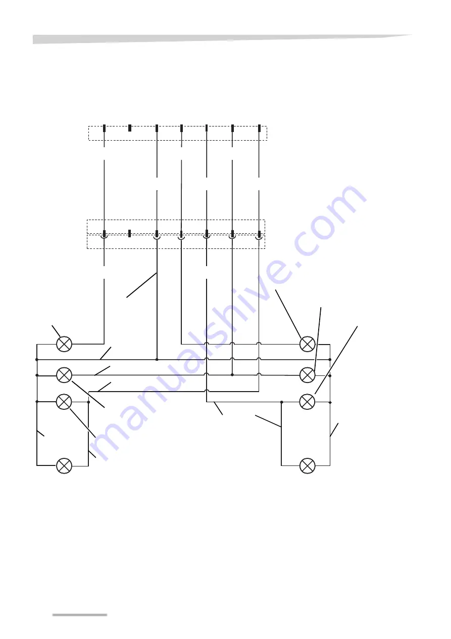
background image

60

Circuit diagrams

Lighting circuit 

diagram

1/L

2/54g

3/31

4/R

5/58R 6/54

7/58L

Yellow

white

green

brown

Red

black

Right blinker

Right brake light

Right rear light

Right side light

Yellow

white

Red
brown

black

white

Left side light

white

black

black

Connector and socket

7-pin in accordance with ISO 1724

Left rear light

Left blinker

Left brake light

Earth

Connector 

7-pin in accordance with ISO 1724

Summary of Contents for Fanex 833 T

Page 1: ...Fanex 833 T Operating manual Edition 11 2007 Date of print 2 2008 Language EN Machine number 6918 0171 Serial number 6918 12 Parts number VF 16644589...

Page 2: ...erneland Group Gottmadingen N V Germany Reproduction transfer to other media translation or the use of extracts or parts of this manual without the explicit permission of Kverneland is not permitted A...

Page 3: ...fety 29 Prior to road transport 30 Road transport 32 Operation 33 Safety 33 Harvest processing 34 Implement Usage 35 Cleaning and care 39 Safety 39 Cleaning 40 Care 40 Parking and storage 41 Safely se...

Page 4: ...he warranty conditions to be met A well functioning implement to remain in good working order Training Your dealer will provide instruction on operation and care of the imple ment Employer information...

Page 5: ...standard version Next to these symbols pictograms are used to help you locate other sections of this manual NOTE The term Note indicates tips and notes on operation The warning triangle indicates imp...

Page 6: ...Numerous risks can result from incorrect handling of agricultural im plements Therefore always work with special care and never under pressure Employer information Inform personnel working with the m...

Page 7: ...Safety instruction 7 Warning symbols on the implement...

Page 8: ...fatal injury can be the result Cardan shaft speed 540 rpm The prescribed maximum cardan shaft speed of 540 rpm must not be exceeded The consequence could be damage to the implement Risk of crushing Ne...

Page 9: ...y Good working condition Ensure that the tractor is always in good working condition and that the tractor s brakes and the implement are working perfectly Observe the information and technical data in...

Page 10: ...d view of the implement which is coupled when it is in both its work and transport positions To do so use at least the panoramic mirror provided by the tractor manufactur er Potential hazardous situat...

Page 11: ...he hydraulic system is often overpressurised All pipes tubes cou plings and connecting passageways must be checked for leaks and other damage on a regular basis Only use suitable tools when check ing...

Page 12: ...y time Riding on the implement is hazardous and strictly prohibited Altered driving and braking performance The driving and braking performance are altered when the implement is attached to the tracto...

Page 13: ...before starting and con tinually during operation Make sure the operator has an adequate view of the work area Only begin work if the immediate vicinity is cleared of any persons or objects There is...

Page 14: ...the tractor and the implement during uncou pling Stop the implement on firm secure level ground Ensure that the sustainer is securely locked Place the cardan shaft in the brackets provided Secure the...

Page 15: ...the cardan shaft drive Depressurise the hydraulic system Whenever possible uncouple the tractor Switch off the electronic control system Switch off the tractor and remove the ignition key Ensure the i...

Page 16: ...connections that are released during maintenance and repair operations must be retightened Serious injuries and dam age to property can be caused by loose bolt and screw connections Further regulatio...

Page 17: ...e on large areas This rotary tedder with a span of 8 30 m and six rotors is ideal for large scale operations Low maintenance gears The implement is equipped with low maintenance gears and seven tedder...

Page 18: ...ons Tine Rotor Running wheel axle Running wheel Rotor arm Rotor gear Sustainer Side equipment Hydraulic cylin der for swivel Central transmission Drawbar Transport latch Hydraulic cylinder for swivell...

Page 19: ...urself with the device 19 Specifications Dimensions Work position m Transport position m Length T 3 10 5 90 Length to bottom reflector A 5 14 Width B 8 63 2 99 Height H 1 25 Height lighting 0 89 Swath...

Page 20: ...24 Hydraulic connections 1 x double acting Hydraulic pressure 130 210 bar Cardan shaft speed 540 rpm Hitch Lift link drawbar or pending attachment Rotors rotor arms tines Number of rotors 6 Number of...

Page 21: ...are missing or have been damaged during transportation please submit a complaint immediately to the dealer importer or the manufacturer Do not assemble the machine yourself Do not perform the assembly...

Page 22: ...ttachment Couple the implement to the lift link drawbar Secure the hitch pin in position a with the split pin Secure the lift link drawbar against accidental lifting This would damage the cardan shaft...

Page 23: ...or backwards Never remove wheel wedges if tractor is not secured against rolling The implement or the tractor could run someone over The conse quence would be serious injury Remove wheel wedges from i...

Page 24: ...d cause accidents Secure the control devices In transport position secure the control devices on the tractor against unintended actuation and lock if possible Unintended actuation of the control devic...

Page 25: ...layout Cable must not show signs of wear or be hanging Torn or frayed cables can cause unforeseen movements on the implement Attach the following electrical cables to the tractor Lighting Lighting of...

Page 26: ...heel wedges The implement must be standing on firm and lev el ground and if necessary must be supported during work Unse cured or non supported implements can cause accidents General The following app...

Page 27: ...ased risk of tipping and injury in a position offset in relation to the direction of the slope There should be no persons standing in the slew range No one is permitted to remain within the slew range...

Page 28: ...ist NOTE The tines should lightly touch the ground Adjust tedder inclination The tedder inclination determines how far the harvest is ejected from the rear Using the eccentric screw on the wheel allow...

Page 29: ...sult in traffic accidents Clean the implement before travelling on the road Before any road transport remove any coarse dirt remaining crops and clods of earth from the implement and clean it Crops or...

Page 30: ...osition of the securing pins for the reset angled position This position must be set on both sets of side equipment Swivel both sets of side equipment with the control lever for the an gled position u...

Page 31: ...should be no persons standing in the slew range No oneispermittedtoremain withintheslew range and working area Personnel canbecaughtby theimplement Thereisotherwisetherisk of serious or fatal injury F...

Page 32: ...immediate vicinity Always ensure an unimpeded view and pay particular attention to any children in the vicinity of the implement When driving lock the control units on tractor Do not transport any per...

Page 33: ...to the condition of the crop Higher speeds can cause dam age to the implement Only allow the cardan shaft coupling to respond briefly Do not let the slip clutch respond for longer than 10 seconds If t...

Page 34: ...un the PTO shaft at roughly 500 rpm Turning ensures uniform drying of the cut crop Run the PTO shaft at roughly 400 rpm Swathing arranges the distributed harvest in little swathes Fit the swathing gea...

Page 35: ...ar distance Obstacles must be circumnavigated in good time and at a distance Due to the width and length of the implement the implement reacts slowly and has an afterrun the implement could be damaged...

Page 36: ...he running wheel latch The running wheels can be secured to allow uniform work to be car ried out on slopes This adjustment is only possible in the work posi tion To do this proceed as follows Align t...

Page 37: ...ed in one direction Adjust limit spreading Set down the implement in the work position and adjust the angled po sition as follows Switch off the tractor s PTO shaft Switch off the tractor engine and s...

Page 38: ...quire ments Adjust working speed to terrain conditions End limit spreading After the end of limit spreading the implement must be brought back to the normal work position before it is folded into the...

Page 39: ...ents Do not clean bearings or hydraulic parts with high pressure cleaners Do not clean bearings or hydraulic parts with high pressure cleaners The high pressurecleaner removes the grease filmfromthe b...

Page 40: ...h pressure cleaner with the excep tion of the bearings and piston rods of the hydraulic cylinders After cleaning After cleaning with the high pressure cleaner lubricate all bearing points Care In orde...

Page 41: ...eed as follows Stop the implement on firm level ground in the transport position Secure the tractor against rolling away switch off and take out the ignition key Secure the implement against rolling a...

Page 42: ...and approved Using other products may lead to malfunctions or re duce safety of operation The use of non OEM replacement parts renders the manufacturer s guarantee null and void and frees the manufac...

Page 43: ...ls Protect your skin by means of protective skin cream or oil resistant gloves Contact can result in skin damage Never use oils for cleaning Never useoilsor lubricantstoclean your hands Burrs andgrit...

Page 44: ...ed from left to right Rotation of screws nuts and suchlike always viewed from the actuation face Task Explanation Greasing Apply grease to the slide surfaces using a brush Greasing Apply grease to the...

Page 45: ...a r L u b r ic a t io n G r e a s in g In s p e c t R e p la c e m e n t C le a n in g P a g e General All screws 46 Visual inspection Bearing 48 Tyre pressure 53 Hydraulic tubes 53 Lighting Lubricat...

Page 46: ...e first 5 operating hours and according to the frequency of use but at least once a season Special tightening torques Take heed of the special tightening torques for the following screw connections 13...

Page 47: ...quality of 8 8 read off the screw head are used NOTE Tighten lock screws and lock nuts to a 10 higher value 20 Nm Screw size Screw quality 8 8 10 9 12 9 M6 9 9 Nm 7 3 ft lbs 14 Nm 10 3 ft lbs 17 Nm 12...

Page 48: ...ess do not press a second time Too much grease will force the bearings apart This could allow dust and dirt to enter the bearing resulting in premature wear Lubricate the places listed in the illustra...

Page 49: ...damaged guard components can cause very serious injuries in operation Lubricate the pivots and their couplings G as follows daily after 20 hours of operation before and after the season after every c...

Page 50: ...be checked again when operated with anoth er tractor Perform an adaptation of the cardan shafts in the following position Couple the tractor to the implement without the cardan shaft Lower the impleme...

Page 51: ...k the oil level of the main gear box and of the tedder gears regu larly Main gear page 52 Rotor gear page 52 The gear boxes must be checked and if there is visible oil loss re filled The illustration...

Page 52: ...mpletely Refill Refill oil until oil seeps out of the check bore Insert the check screw and tighten Wipe up any oil spills immediately Rotor gear The gear has sufficient oil if oil seeps out of the ch...

Page 53: ...ding Do not perform any welding work in the vicinity of the hydraulic hoses Hydraulic oil can burst into flames very easily Clean hydraulic system Close or disconnect the quick release coupling with g...

Page 54: ...parallel over the whole length Correct the tine position Correct tine position Correct the tine position of each tine when changing the times and once before the season Release the hex nut and lock n...

Page 55: ...swathing gear reduces the speed of the cardan shaft The crop is not dispersed but deposited betweentwo ro tors as a swath Remove the existing protective shield on the central transmission Slide the s...

Page 56: ...he implement into the work position Release the running wheel latch see Release the running wheel latch page 30 Pull the cable control ball valve cable and keep it taut Drive slowly forwards until the...

Page 57: ...eavily contaminated Working depth set too low Implement not operating cleanly at high speed Rotor tines set too high Uneven terrain Speed too fast to process the amount of fodder Reduce speed Friction...

Page 58: ...agrams Circuit diagrams Hydraulic diagram standard version Hydraulic coupling stop valve Left hydraulic cylinder for swivelling Orifice plate 0 5 mm Drawbar cylinder Right hydraulic cylinder for swive...

Page 59: ...c cylinder Stop valve Hydraulic coupling Left hydraulic cylinder for swivelling Cable control ball valve angled position Right angled position hydraulic cylinder Orifice plate 0 5 mm Drawbar cylinder...

Page 60: ...rown Red black Right blinker Right brake light Right rear light Right side light Yellow white Red brown black white Left side light white black black Connector and socket 7 pin in accordance with ISO...

Page 61: ...of properly without damaging the en vironment Please observe the currently valid waste disposal guide lines Metal parts All metal parts must be disposed by a metal recycler Oil Hydraulic fluid must be...

Page 62: ...ichthis declaration relates complieswith the relevant basic safe ty and health requirements of the EC Directive 98 37 EC The following standards were applied to achieve EU directive con formance on he...

Page 63: ...e season 41 uncoupling 41 Information on the implement 17 L Limit spreader Adjusting 37 Hydraulic 56 Manual 37 Resetting 30 Limit spreading 37 Lubrication points 48 51 Cardan shafts 49 General 48 51 M...

Reviews: