background image


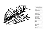
Horizontal thruster assembly 

55 

propeller guard 

56 

propeller cap nut 

57 

propeller 

58 

propeller guard mounting ring 

59 

filter bushing 

60 

thruster cone 

61 

thruster cone nut 

62 

thruster cap nut 

63 

thruster cap 

64 

sealing ring  

65 

thruster rod 

66 

thruster 

67 

motor mounting washer 

68 

thruster mounting washer 

69 

thruster tube 

70 

sealing ring 

71 

thruster closure backwall 

72 

sealing ring 

73 

light port 

74 

sealing ring 

75 

closure backwall nut 

76 

sealing ring 

77 

hull spacer 

78 

nut 

79 

washer  

80 

screw 

81 

inside magnetic coupling 

82 

outside magnetic coupling 

83 

Screw 

84 

thruster  bushing 

85 

filter 

86 

propeller shaft 

Сборочный чертеж движителя

Horizontal thruster assembly


Summary of Contents for GNOM BABY

Page 1: ...Y Operator manual Vapenicka 24 971 01 Prievidza Slovakia Tel Fax 421 46 54264 56 https www vftech sk https www rov 2020 remotely operated vehicle VFTECH spol s r o Vapenicka 24 971 01 Prievidza Slovak...

Page 2: ...hnical specifications 6 2 User s manual for operation with GNOM 7 3 Keys and Buttons at the control panel 12 4 Screen modes 15 5 Calibration 16 6 Maintenance operation 17 7 Safety requirements 19 8 Wa...

Page 3: ...ayed on the monitor TV receiver or sent to the digital video recorder if supplied via standard AV cable There are two video output connectors at surface control module that allow to connect two displa...

Page 4: ...v09 2020 4 1 DESCRIPTION 1 2 DESIGN Recommended configurations Hand reel Coaxial cable Underwater module Power supply control module Joystick Waterproof transport cases LCD monitor...

Page 5: ...hts main hull The plastic float is fastened by the nut and the Screw propellers are installed at the end of the thruster ax the power supply converter electronic module and depth sensor are installed...

Page 6: ...ressing one of the buttons on the joystick the operator can enter the menu to tune up some of the functions such as calibrating of the depth sensor 1 2 TECHNICAL SPECIFICATION 3 magnetically coupled t...

Page 7: ...of the vehicle by adding additional weights on the plastic feet Note that the cable weight in water is approximately 2 g m 2 3 Plug the 3 pin connector to the reel and video cable to the monitor video...

Page 8: ...he RCBO Checking the RCBO residual circuit breaker with overcurrent protection must be performed before any underwater operation at the new location If the requirements of paragraph 2 4 1 are met conn...

Page 9: ...s the arrows Left Right Up Down power use the left joystick right joystick ANALOG HOME v09 2020 USER S MANUAL FOR OPERATION 30V ON UP position switch it on separately Brightness contrast on can be adj...

Page 10: ...1 or Mode2 or Mode3 see below You can choose the menu language Russian English SELECT L 1 L 2 R 2 R 1 R 2 v09 2020 USER S MANUAL FOR OPERATION to change the intensity of the front 100 100 0 Press 100...

Page 11: ...h water Special Functions Sleep mode Power Saving Mode In order to save the power and extend the battery life the wireless joystick has a power saving mode The joystick enters sleep mode power saving...

Page 12: ...v09 2020 12 3 KEYS AND BUTTONS AT THE CONTROL PANEL...

Page 13: ...v09 2020 13 3 KEYS AND BUTTONS AT THE CONTROL PANEL...

Page 14: ...v09 2020 14 3 KEYS AND BUTTONS AT THE CONTROL PANEL...

Page 15: ...v09 2020 15 4 SCREEN MODES...

Page 16: ...calibrate the compass follow the Calibration procedure 1 Put the GNOM on flat surface away from metal objects with the dome pointing North 2 Press circle right key to start the calibration 3 Slowly tu...

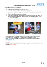
Page 17: ...rication of propeller shafts every time after diving Oil must get inside the cone shaped heads of motors See appendix position 96 147 217 of thruster assembly to avoid nods and twisting of cable Withi...

Page 18: ...cover VULCANIZING TAPE use for temporary repair of damaged cable damaged insulation FUSES use if the fuses installed in the power module are destroyed SEALING O RINGS use if the cable in the underwate...

Page 19: ...on and off by main 230V switch which is placed over the power cord on the surface control unit 3 Do not use the system with the damaged cable 4 Do not touch the underwater vehicle and the cable if you...

Page 20: ...arranty does not apply to defects that have been caused by not following the recommended installation or maintenance procedures Neither the defects resulting from normal wear tear incorrect operation...

Page 21: ...v09 2020 21 9 EXAMPLES OF MODULE LINKING...

Page 22: ...v09 2020 22 9 EXAMPLES OF MODULE LINKING...

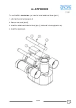
Page 23: ...To use GNOM in fresh water you need to install additional floats pos 1 1 Unscrew the skid screws pos 3 2 Remove the skids pos 2 3 Install the additional floatation block pos 1 enclosed in the equipme...

Page 24: ...V 50 60 Hz Main board 48V Control Video F2 connection cable Joystick Power video and control cable 48V monitor Hand reel RCBO Residual Current Circuit Breaker with Overcurrent Protection 16A 10iA F1 f...

Page 25: ...lister body 7 camera body 8 PCB fixing ring 9 horizontal thruster 10 rear cover assembly 11 float fixing stud 12 cable clamp 13 vertical thruster 14 horizontal thruster 15 screw 16 thruster mounting 1...

Page 26: ...5 back cover 36 back cover retaining ring 37 sealing ring 38 vertical thruster mounting 39 sealing ring 40 cable pressure seal 41 sealing ring fastening 42 cable pressure seal bush 43 washer 44 screw...

Page 27: ...ring 65 thruster rod 66 thruster 67 motor mounting washer 68 thruster mounting washer 69 thruster tube 70 sealing ring 71 thruster closure backwall 72 sealing ring 73 light port 74 sealing ring 75 clo...

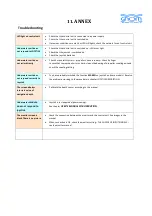
Page 28: ...hard clean slide bearing of propeller coupling axis and check the coupling setting Underwater unit does not respond correctly to Joystick You have probably switched the function MAKRO on joystick on s...

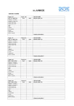
Page 29: ...VERTICAL THRUSTER B LIGHTS SERVO COMPASS DEPTH SENSOR JOYSTICK CONTROL UNIT MOTOR COUPLING STAMP AND SIGNATURE Coupon No 3 Date of sale SERIAL NUMBER DATE OF INSPECTION TRUE FALSE REPAIR DESCRIPTION...

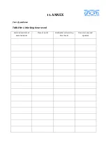
Page 30: ...11 ANNEX Year of purchase TABLE 1 Working time record Start and end date of executed works Place of works Underwater unit working time hours Operator name and signature...

Page 31: ...d parameter of network fuse Type and parameter of power cable fuse 180V Operator name and work position Signature 1 2 3 4 5 Table No 3 Inspection of coaxial cable intactness Date Type of cable Result...

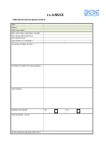
Page 32: ...yee accepting the complaint Date of accepting the complaint Date of product sale Type of product serial number Description of defect by client Description of defect by service operator Used material L...

Reviews: