background image


10

/

14


5. Laser GRBL software 

    Laser GRBL is an excellent and practical opening source controls software in the field of laser engraving. Compared 
with similar software, it has a simple interface, simple operation, and supports multiple languages. There are a lot of 
learning resources used on the Internet, which is convenient for beginners to understand and master the software. 
Mastering a laser engraving software is the basic condition for using laser engraving machine. It is recommended that 
beginners first learn the operation method of the software online before using it to prevent damage to the laser 
engraving machine and surrounding items by improper operation. 

5.1 Download and installation


    Download from Laser GRBL official website or ask our customer service to get the archive contains two files: 
(1) CH340 USB driver Unzip the package and find the file 

DRVSETUP64.exe

. Double-click to install, the user needs to 

install this driver when running the software for the first time. 
(2) Laser GRBL software locate the file (install.exe) in the archive, double-click it to install it. 

5.2


Online operation steps 


Online operation is the operation of controlling the device through software after the device is connected to the 

computer.


(1). Connect the device to the computer with a USB cable. 

(2). Place the material to be engraved in the working area of the engraving machine. Turn on the weak light, focus by 
rotating the laser focus knob until the spot becomes smallest and clearest, then the focus is complete. 

(3) Open the Laser GRBL software, select the COM port (except COM1, you can plug and unplug the USB cable to see 
which one is) and the baud rate (generally set to 115200), then click the connection, the color of the button will become 
darker after the connection is successful (if Click the connect button and the color does not become darker. You can 
unplug the USB cable and plug it in again.) 

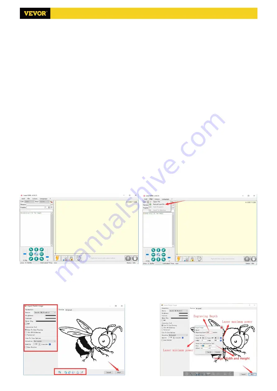
(4). 

Af er  he connec ion is s ccessf l, click  File  on  he men  bar of  he in erface  o en er  he selec ion file in erface, 

selec   Open File , impor   he pic re  o be 

engraved, etc.


(5). 

Selec   he file  o be engra ed, click  Open ,  he 

Inp  Ras er Image

dialog box will pop up. Here is the setting engraving mode and some other engraving 

parame ers. Click  Ne

 af er se ing.


(6). 

Click  Ne

  o pop  p  he  Targe  Image  dialog bo ,  here  o  can se   he engra ing speed, minim m po er 

and maximum 

po er and  he leng h and  id h of  he image  o be engra ed and offse . Click  Crea e  af er se ing.


S3018 Pro Ver 2.3

Summary of Contents for S3018 Pro

Page 1: ...ncy Shutdown steps first cut off the power then pull out the USB cable Precautions 1 All parts description just for illustrative purpose If there is any difference please refer to the actual part shap...

Page 2: ...e 4P 3 18 Hand knob X Y 8 18mm 2 C6 Spindle motor ire 2P 1 19 Hand knob Z 5 18mm 1 20 Inner he agon scre M5 16 12 21 Inner he agon scre M5 20 20 C8 USB cable 1 22 Inner he agon scre M3 14 4 C9 Po er s...

Page 3: ...M4 5 1PCS Set Screw for knob 20 M5 16 12PCS Screw 05 Connecting plate back 1PCS 13 Stepper motor 1PCS 22 M3 14 4PCS Screw 18 8 18mm 1PCS Hand knob Y 04 Connecting plate font 1PCS D i r e c t i o n o...

Page 4: ...Screw 4PCS 13 Stepper motor 1PCS 23 M3 18 screw 4PCS D irection of connecting w ire 06 Connecting plate left 1PCS 25 Trapezoidal nut M5 20 6PCS 21 M5 20 Screw 10PCS 18 Hand knob X 8 18mm 1PCS 27 M4 5...

Page 5: ...Step 5 14 The plastic column must be assembled between the control board and the aluminum parts C4 M5 10 4PCS Ship nut C1 Control board 1PCS C2 Column 4PCS C3 M5 10 4PCS Screw S3018 Pro Ver 2 3...

Page 6: ...lease lay the materials to be engraved flat under the laser The recommended distance from laser outlet to materials is 3 10cm Out of range may be out of focus Turn on the weak light Rotate the focusin...

Page 7: ...later use Restore X Y Z Restores local system coordinates with G92 command Safe Z Moves tool by Z axis to safe position Position coordinate can be specified in the Safe Z setting Position must be spec...

Page 8: ...nterface click Open to select a G code file that has been made to import the file After importing the middle of the interface will display a visual graph composed of tool paths the position of the pen...

Page 9: ...ance of one sheet of paper for engraving and then return the X Y and Z axes to zero please use a flat bottom sharp knife when engraving and use a cylindrical milling cutter when machining planes slots...

Page 10: ...ion is the operation of controlling the device through software after the device is connected to the computer 1 Connect the device to the computer with a USB cable 2 Place the material to be engraved...

Page 11: ...hoose low power Q Which formats are supported Support all formats of images support GCODE NC files If you want to engrave DXF file please use the VigoWorks software Visit our website www VevorEngraver...

Page 12: ...ess to open the spindle corresponding to SPN gray on the screen press again to close the spindle the corresponding SPN on the screen returns to normal Long press to enter changing spindle speed page A...

Page 13: ...is a dot in the upper left corner of the main page The RED dot indicates that VIGO STK hotspot is active and the GREEN dot indicates that the controller has connected to Local WiFi The web management...

Page 14: ...dows and run it Click the button Connect After the software connected the machine successfully click Settings On the settings window Click Restore Factory button then reboot the machine Method 2 Run C...

Reviews: