VESTEL EVC04-AC Series Service Manual Download Page 7


 Page 7 of 64  


MECHANIC SPECIFICATIONS 

Material


Plastic


Size


315 mm  (Width) x  460 mm (Height) x  135 mm (Depth)


Dimensions (Package)


405 mm  (Width) x  530 mm (Height) x  325 mm (Depth)


Weight (Product)


5 kg for socket equipped model, 6,8kg attached cable model


Weight with package


7,1 kg for socket equipped model, 8,9kg attached cable model


AC Mains Cable Dimensions


For 22 kW version Ø 15-21 mm 
For 11 kW version Ø 15-21 mm


Cable Inlets


For 7.4 kW version Ø 11-15 mm 
AC Mains / Ethernet / Modbus


ENVIRONMENTAL TECHNICAL SPECIFICATIONS


Protection Class


Ingress Protection 
Impact Protection


IP54 
IK10


Usage Conditions


Temperature


Humidity 
Altitude


-

35 °C to 55 °C (without direct sunlight) (–

25°C to +50 °C for RCCB equipped models) 
5% - 95% (relative humidity, no dew)


0 - 4,000m


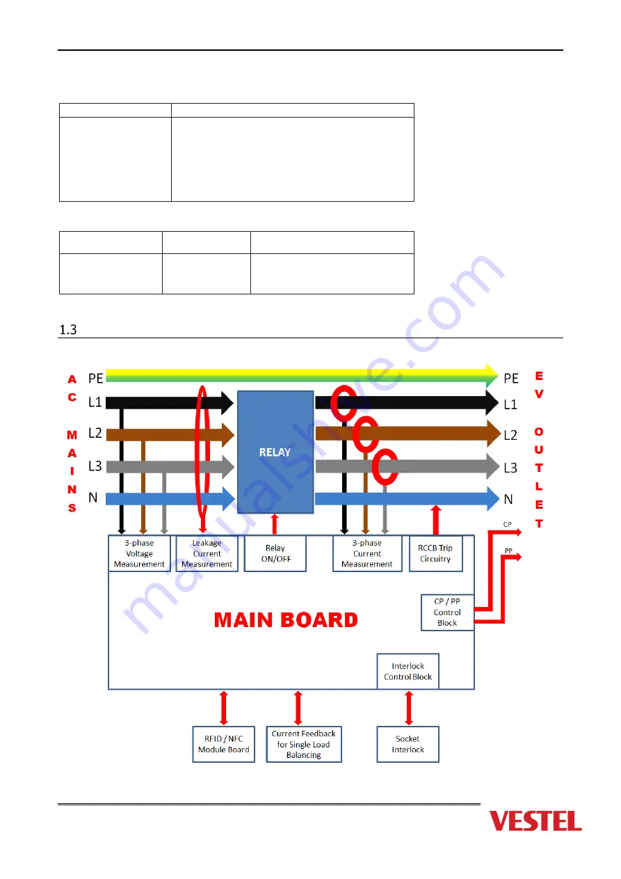
System Block Diagram 


Figure 1-3 

Summary of Contents for EVC04-AC Series

Page 1: ...Page 1 of 64 EVC04 AC22 AC7 4 SERVICE MANUAL...

Page 2: ...64 Revision History First Version U ur Korcan ten Second Version Overcurrent and under voltage values Third Version Smart Model extension Fourth Version Fifth Version Sixth Version Seven Version Eigh...

Page 3: ...llation 16 Changing Main Board 17 General Information and Warnings 17 Changing HMI Board Smart Model 25 Changing Display Smart Model 27 Changing RFID Board 28 Changing LED Board 30 Changing WiFi Board...

Page 4: ...words and phrases are written in a different format to get your attention Note It is being used to put emphasis on useful information and critical points regarding the product WARNING CAUTION Disconn...

Page 5: ...combinations of W and L Blank No connectivity module except RFID reader S Smart Board with Ethernet Port W Wi Fi module or WiFi Bluetooth module L LTE 3G 2G module 3rd Asterisk Can be one of the follo...

Page 6: ...x4 mm 50 m External Dimensions 15 21 mm CONNECTIVITY Connected Models Ethernet 10 100 Mbps Ethernet Standard with Smart Options Wi Fi Optional Wi Fi 802 11 a b g n ac OTHER FEATURES Connected Models R...

Page 7: ...ipped model 8 9kg attached cable model AC Mains Cable Dimensions For 22 kW version 15 21 mm For 11 kW version 15 21 mm Cable Inlets For 7 4 kW version 11 15 mm AC Mains Ethernet Modbus ENVIRONMENTAL T...

Page 8: ...er Input 6 Veslink connection socket 21 Protective Earth 7 LOG connection socket 22 Protective Earth 8 J TAG DEBUG socket 23 Relay output terminal N 9 CP PP connection socket 24 Relay output terminal...

Page 9: ...Page 9 of 64 RFID Module Top View NO COMPONENT 31 RFID Connection Socket Table 2 3 31...

Page 10: ...Page 10 of 64 LED Board Top View Back View NO COMPONENT 32 LED Connection Socket 32...

Page 11: ...cket 3 Micro SD Card Socket 4 Wifi Module Socket 5 External RS485 Connection Socket 6 USB Connector 7 Micro USB Connector 8 PLC Module 9 GSM WCDMA LTE Module Socket 10 GSM WCDMA LTE Module Power Socke...

Page 12: ...Page 12 of 64 LTE Board Smart Model Top View NO COMPONENT 1 HMI Socket 2 Power In Socket HMI 3 Main Antenna SMA Connector 4 Diversity Antenna SMA Connector 5 SIM Card Connector 3 4 1 2 5...

Page 13: ...Page 13 of 64 Wi Fi Board Smart Model Top View NO COMPONENT 1 HMI Socket 1...

Page 14: ...1 LED Light Color Indications Ready No Light Charging Blue Glowing Waiting For Authorization Blinking Blue Charging Authorized Green Glowing Fault Steady Red Charging Disabled Steady Purple Charging...

Page 15: ...user manual and installation guideline inside the product package carefully before installing servicing and operating the EVC If the LED is steady Red please check troubleshooting section in user manu...

Page 16: ...r 1x Torque T25 Security Screwdriver 1x Torque T20 Screwdriver 1x Allen Screwdriver 4 1x Allen Screwdriver 3 1x Phillips PH2 PH3 P4 P5 P6 Screwdriver 1x Flat Slot type Screwdriver 1x Spirit Level Wate...

Page 17: ...make sure to be complete following operations before starting any repair or disassembly I Shut down AC mains energy supply from MCB and RCCB Important If EVC is energized do not disassemble the device...

Page 18: ...ct AC Mains input cables to the mainboard then RCCB Step 14 Place the isolation sheet on the mainboard Step 15 Place and screw RCD cover Step 16 Place and lock RCD housing Step 17 Close the front cove...

Page 19: ...cover on the left side of the charging station Place and push the triangle key on the side cover lock then rotate the key 90 degree counter clockwise Important Isolation plates are Safety critical com...

Page 20: ...t must be connected properly to the mainboard See 2 Board Layout section 2 1 Mainboard Two protective earth cable connected on output terminals 21 and 22 If it is a smart EVC04 model and there is HMI...

Page 21: ...les on RCCB between main board and RCCB Unscrew AC Mains cables on RCCB figure 4 2 Unscrew AC Mains cable on the main board 1 2 3 4 5 in figure 4 3 Pull the AC Mains input cables from RCCB through the...

Page 22: ...ables 1 2 3 4 output cables 23 24 25 26 and protective earth cables 21 22 board power input cable 20 LED cable 19 RFID cable 15 Earth and data cables between ACPW and HMI only for Smart models 16 30 R...

Page 23: ...emove main board Remove main board from the bracket Step 9 Change main board Step 10 Place the main board to the bracket Remove the protective materials or labels on sockets switch SW1 and buzzer BZ1...

Page 24: ...1 check figures between previous steps 3 and 4 for isolation sheets Check cable clamps are mounted in figures C1 and C2 Also check figures Back Cover and Front Cover below Check the hinge bracket is m...

Page 25: ...Change the board Step 6 Place and screw the new board Step 7 Connect the cables Step 8 Close the front cover screw the back cover Step 9 Check the system operation Step 1 Unscrew the back cover and o...

Page 26: ...e new board Screw the top left corner of the board with earth connection coming from the main board as shown in the figure H2 Step 7 Connect the cables Connect the cables back to the sockets on HMI Bo...

Page 27: ...ange the display first remove the LCD Housing as shown in figure below Unscrew HMI Board as shown in the previous section Changing HMI Board Two double sided tapes are mounted as shown the left side o...

Page 28: ...APE_DOUBLE_SIDE 40X50X1 VESTEL RFID such that the socket on the board stays above as shown in the figure R1 For Base model No HMI Board RFID board is connected to the main board ACPW See 2 Board Layou...

Page 29: ...Page 29 of 64 For Smart models models with HMI Board RFID Board is connected to HMI Board as shown in figure below...

Page 30: ...Main Board To demount LED board first you need to demount interlock and output socket See next sections Changing Interlock and Changing Output Socket 21EVCL01 LED Board is mounted on the cosmetic fram...

Page 31: ...as shown in the figure passing through the cable clamps 2 3 and then tied with cable ties 4 5 marked by circles The ferrite on the ACPW Led cable on ACPW side is attached to the metal plate 5 6 as sho...

Page 32: ...le sided tapes on the WiFi Board as shown in figure W1 below Mount the WiFi Board as shown in the figure W2 below Connect HMI to WiFi cable as shown in the figure below WiFi Board Black end of the cab...

Page 33: ...ted to CN5 on LTE Board and CN18 on HMI Board Unscrew the LTE Board as shown in figure L1 below Note that there is a ferrite clamp mounted on the HMI LTE cable CABLE EVC 10P 90 1 25MM AWG28 GSM HMI as...

Page 34: ...remove the interlock first Connect the interlock cable back to the interlock and to the interlock socket Board Layout 5 on mainboard Screw the interlock back Make sure the cable is passing through th...

Page 35: ...m allen key 1Nm torque You can see the screw points in figure 3 the side of the socket Unscrew the CP PP cables from the side pointed by arrows of the socket slotted 4mm tip Unscrew the socket screws...

Page 36: ...1x terminal rail RAIL CONNECTOR KLEMENS EVC04 on the back cover and mount the 5 terminals KLEMENS RAIL TYPE W SCRW DC10 01P 11 00A as in figure ET1 Mount the 1x terminal cover KLEMENS COVER RAIL TYPE...

Page 37: ...ve earth cable is passing outside the ferrite cores NOT inside following the path b e d RCCB Connection see figure 5 4 1 in section 5 4 under next section 5 RCCB and DC6mA Cable Line Color 1 E Yellow...

Page 38: ...hanging Interlock and Changing Output Socket Cosmetic frame is screwed on the front cover as shown in figure CF1 below with PH2 bit 0 5Nm torque Cable clamps CABLE_CLAMP_CCB1 are mounted such that the...

Page 39: ...gure 5 1 1 FUSE SAFE RCCB 40A 4P TYPE AI 30mA is mounted on the RAIL as shown in figure 5 1 2 DC6mA sensor is mounted on METAL PLATE and as shown in figure 5 1 3 DC6mA connector can be mounted on the...

Page 40: ...erminal side are passed through the DC6mA sensor and goes through the mainboard as shown in the fig re DC6a The line cables from the mainboard input side are terminated on RCCB as shown in the figure...

Page 41: ...ET_SIDE_COVER_EVC04 left in the figure below is mounted on the RCCB as shown in the middle in figure below The housing HOUSING_3P_RCCB_EVC04 is mounted with two cross head screws as shown in the figur...

Page 42: ...D 3 the gap must be on upper left on rear side of LOCK BOLT WIDE EVC04 R1 To demount that part use triangle key on part RCD 2 to hold the material tight and use a PH2 type screw driver on RCD 4 RCD 3...

Page 43: ...in figure 6 1 for wall installation For stand installation 1 and 2 will be replaced See STAND IG document For models with cable there is a gland nut RAKOR M32X1 5 15 21 RAL9005 instead of plastic blin...

Page 44: ...ection cable and special cable Cable 7 of Veslink to download software to selected IC 4 WG VESTA Veslink device 6 1 2 Installing Software to Veslink Step1 Download VESTEL Veslink Programmer to a PC Se...

Page 45: ...grammer and select TI MSP430F67X51AIPZ as microcontroller for main control software update Figure 5 3 Step 4 Select open and choose your SW based on hex file which you want to download your main contr...

Page 46: ...h USB cable Figure 5 5 Veslink screen is changed with name of your SW hex file name as shown in Figure 5 6 after downloading Figure 5 6 Step 6 Firstly make sure that EVC is de energized and make conne...

Page 47: ...Figure 5 9 Figure 5 10 1 PROG Button This button is downloading SW to main board MCU If the SW is downloaded in Veslink before you can direct to start Step 7 to download SW to main board without PC 2...

Page 48: ...mpletes the screen is shown as Figure 5 13 Figure 5 12 Figure 5 13 If the SW is installed in WG VESTA Veslink device once use only Step 7 to download SW to the microcontroller without PC Important Bef...

Page 49: ...Page 49 of 64...

Page 50: ...VC TESTER AND MOBILE APPLICATION Figure 7 1 Veslink device and required cables tools to get log Vestel EVC Configurator mobile application must be downloaded from play store for android mobile phones...

Page 51: ...following connections between mobile phone EVC Tester and EVC Figure 7 2 Cable connections between EVC tester EVC main board and mobile phone Step 2 Open Vestel EVC Configurator application on your m...

Page 52: ...ayed with S prefix Possible states are as follows A1 Pilot State Unplugged No Cable A2 Pilot State Unplugged PWM B1 Pilot State Plugged in Vehicle connected B2 Pilot State Ready Vehicle connected and...

Page 53: ...or 6 2 sec CP voltage is between 1 to 1 V Auto Immediately Over voltage phase 1 7 5 sec 270 V Auto Immediately Over voltage phase 2 8 5 sec 270 V Auto Immediately Over voltage phase 3 9 5 sec 270 V Au...

Page 54: ...occurs 3 times sequentially then permanent error occurs A1 state Immediately Power Optimizer Phase 1 Communication Error 21 In 1 Phase Product 10 sec In 3 phase product 30 sec Communication error occ...

Page 55: ...Page 55 of 64...

Page 56: ...Page 56 of 64...

Page 57: ...Page 57 of 64...

Page 58: ...Page 58 of 64...

Page 59: ...Page 59 of 64...

Page 60: ...r input terminal Be sure to connect L1 L2 L3 N and Earth correctly Three phase Figure 8 1 Three Phase Single Phase Electric Terminal AC Cable Color Electric Terminal AC Cable Color 1 AC L3 Grey 1 AC L...

Page 61: ...Page 61 of 64...

Page 62: ...rging station This relay must not be at transmission except for charging mode There mustn t be any voltage on socket of station outlet If the charge socket of device has line voltage except for chargi...

Page 63: ...ard of charger or the PP connection of the charger s output socket The mainboard must be replaced to solve this problem If this error occurs while the electric vehicle charger cable is plugged in the...

Page 64: ...to recover mechanism waits for cable unplug If charging cable is unplugged and error conditions are removed then error is cleared after 10 seconds The mainboard must be replaced if the problem is stil...

Reviews: