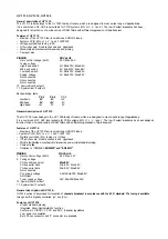


OPTION 01
B7B6B5B4B3B2B1BO
B 7 = F o r f : 1 (Motel)
B6= Fors: 1 (Note 1 )
B5 = DL : X (De-interface: 0= Interface, 1= De-interlace) (don't care)
B4 = STB : X (Stand-by) (0= TDA884X in standby mode, 1= 1C
operational) (don't care)
B3 = Poc : X (Synchronisation mode: 0=Synchronization active,
1 =Synchronisation not active) (don't care)
B2 = Cm2 : X (Note2) (don't care)
B1 = Cm1 : X (Note2) (don't care)
BO = CmO : X (Note2) (don't care)
Note-l:
Forf, Fors bits: Forced field frequency: This forces the vertical divider in a 60 Hz mode or automatic. In auto mode it can be
given a preference for 50 or 60 Hz or to keep the last detected field frequency.
FORF FORS Vertical Frequency
0 0 Auto, 60 Hz if not locked
0 1 60 Hz forced (Note c)
1 0 Auto, keep last detected frequency
1 1 Auto, 50 Hz if not locked
Note c: When already locked at 50 Hz, 60 Hz is forced after sync loss.
Note2:
Cm2, Cm1, CmO bits: Colour Decoder Mode: With these bits the automatic mode can be selected or the decoder can be forced to
one of the standards. Xtal selection bits XA and XB should not be contradictory to a forced Xtal selection in the colour decoder
mode (e.g. force pin 35 while there is only a Xtal on pin 34).
CM2 CM1 CMO Colour Decoder Mode
0
0
0 Automatic, own intelligence, 2 Xtals
0 0 1 Forced Xtal pin 34, PAL/NTSC
0
1
0 Forced Xtal pin 34, PAL
0 1 1 Forced Xtal pin 34, NTSC
1 0 0 Forced Xtal pin 35, PAL/NTSC (Note d)
1 0 1 Forced Xtal pin 35, PAL
1 1 0 Forced Xtal pin 35, NTSC
1 1 1 Forced Xtal pin 35, SECAM
Note d: In this mode, the colour oscillator is forced to use one Xtal pin, while the decoder can select PAL or NTSC automatically.
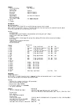
OPTION 02
B7B6B5B4B3B2B1BO
B7 = Oso : 0 (Over-scan Switch-Off: 0= Switch-off undefined,
1 = Switch-off in vertical overscan)
B6 = Vsd : 0 (Vertical Scan Disable: 0=Ac1ive Vertical Scan,
1 = Disable Vertical Scan)
B5 = Cb : 0 (Chroma Band pass center frequency: 0= Centre frequency at
Fsc (chroma sub-carrier frequency), 1= Center frequency at
1.1'Fsc)
B4 = Bis : 0 (Blue Stretch: 0= Blue Stretch off, 1 = Blue Stretch on)
B3 = Bks : 0 (Black Stretch: 0= Black Stretch off, 1= Black Stretch on)
B2 = le1 : X (Insertion Enable Fast blanking: 1= enable RGB insertion,
0= disable) (don't care)
B1 = Afw : X (AFC Window around IF center frequency: 0= Nominal
window, about 80 kHz wide; 1= Enlarged window, about 240 kHz
wide) (don't care)
B0= Bb : 0 (Blue Background: 0= Normal operation, 1= Blue
background active)
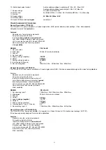
OPTION 03
B7B6B5B4B3B2B1BO
B7 = Hob: Note!
B6 = Bps: 0 (Bypass chroma delay line: 0 Chroma delay line active, 1=
Delay line bypassed)
B5 = Acl: X (Automatic Colour Limiting: 0= ACL not needed for
standard burst/chroma transmissions; 1 = ACL active, for non
standard chroma-to-burst ratio) (don't care)
B4 = Cmb: Note2
B3 = Ast: X (Abs-loop Start-up mode: 0=Automatic mode, RGB drive
switches on when ABS loop stable; 1 = Switch-on under control of
micro controller) (don't care)
B2 = CL2: 1 (Note3)
B1 = C L 1 : 1 (Note3)
BO = CLO: 0 (Note3)
23
Summary of Contents for 11AK19
Page 1: ...SERVICE MANUAL CHASSIS 11 AK19 FIRMEN EUROLINE PALLADIUM S E G TECHLINE VESTEL...
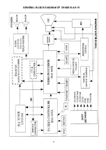
Page 27: ...GENERAL BLOCK DIAGRAM OF CHASSIS AK19 26...
Page 30: ......
Page 31: ......
Page 32: ......
Page 33: ......
Page 34: ......
Page 35: ......
Page 36: ......
Page 37: ......
Page 38: ......
Page 39: ......


