Vestax Corporation
MAR.2004 VMC-002E
q
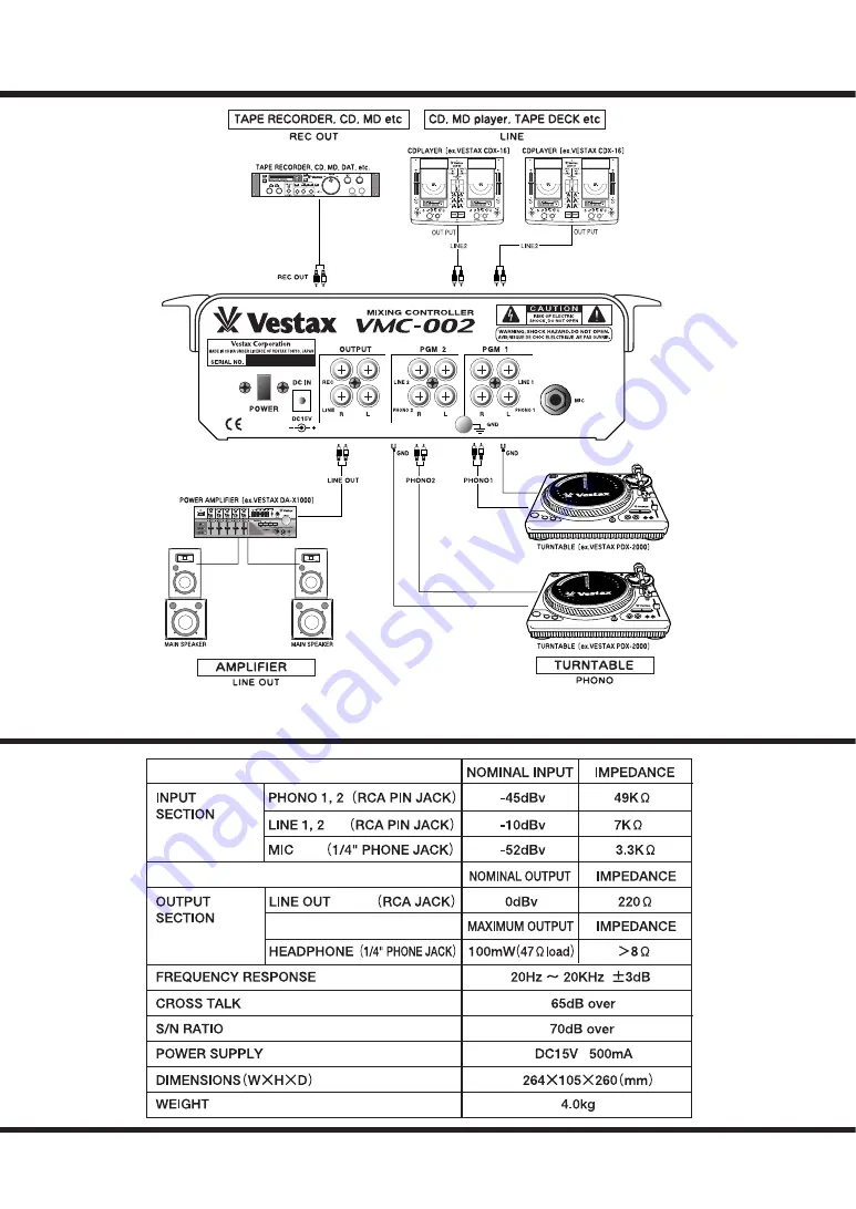
CONNECTION DIAGRAM [example]
S P E C I F I C A T I O N S
Page 1: ...0ISTURE C A U T l 0 N T O R E D U C E T H E R l S K O F E L E C T R l C S H O C K D O N O T R E M O V E C O V E R O R B A C K N O U S E R S E R V I C E A B L E P A R T S I N S I D E R E F E R S E R V...
Page 2: ...tion the fader unit carefully and secure with screws You can replace the CF unit with CF RUS CF R or CF PCV HOW TO REPLACE THE CF UNIT WITH CF PCV When the fader unit is replaced please see fig C Plac...
Page 3: ...same characteristics as the original parts Unauthorized substitutions may result in fire electric shock or other hazards 17 Safety Check Upon completion of any service or repairs to product ask the s...
Page 4: ...3CF MONITOR VOLUME Crossfader signal to be monitored from each program 4MIC LEVEL VOLUME Adjusts the input level of the MIC INPUT 3 qPOWER INDICATOR Lights up when the POWER SWITCH 7 is on wINPUT SEL...
Page 5: ...nnels when Phono input is selected 2LINE OUT JACK Connect to the input of power amplifier 3REC OUT JACK Connect to the input jack of the tape recorder MD DAT etc The output level of this jack is fixed...
Page 6: ...uld not be placed in a built in installation such as a bookcase or rack unless proper ventilation is provided or the manufacturer s instructions have been adhered to 10 Power sources This product shou...
Page 7: ...Vestax Corporation MAR 2004 VMC 002E q CONNECTION DIAGRAM example SPECIFICATIONS...
Page 8: ...OWNER S MANUAL...