Item no.: 960314.R5
Date 2006-09-11
Issued by: Technology
Class: II
Type: MAN
Page 4 of 32
Safety Regulations for Operators and Technicians
V90 – 3.0MW/V100 – 2.75MW
Vestas Wind Systems A/S · Alsvej 21 · 8900 Randers · Denmark · www.vestas.com
4.
Controller and Operating Panel
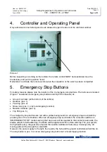
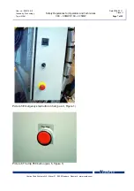
Only authorised or instructed persons are allowed to open the doors of the controller cabinet.
Picture 1
Before inspecting or working on the turbine, the remote control MUST be deactivated. Use the
breaker-key and set it in position “local”.
Remember to activate the remote control when the inspection or the work has been completed.
5.
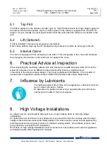
Emergency Stop Buttons
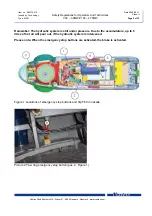
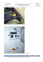
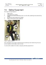
For safety reasons please note the location of the 4 emergency stop buttons. The buttons are located
(Figure 1 Locations of emergency stop buttons and trip F60 in nacelle) at:
•
Ground controller (at the bottom of the turbine).
•
Gearbox (pos. 1).
•
Yaw ring (pos. 2).
•
Nose cone (pos. 3, only local stopping function)
•
Nacelle controller (pos. 4).
•
Trip F60 (pos. 5).
The emergency stop buttons are red with a yellow background. An emergency stop is activated by
pressing one of the red buttons. When an emergency stop is activated, the controller switches to
“EMERGENCY STOP” mode meaning that no power will be supplied to the contactor solenoids, the
blades will pitch (full feathering), the brake will be applied and the turbine will stop. The yaw system,
the hydraulic pump, the gear oil pump and the nacelle ventilator will also stop. Consequently, all
moving parts will be brought to a standstill.
However, the power supply to the light, the nacelle, the hub and the ground controllers will still be on.
The stop button in pos. 3 is not an emergency stop button but a local stopping function.

