background image

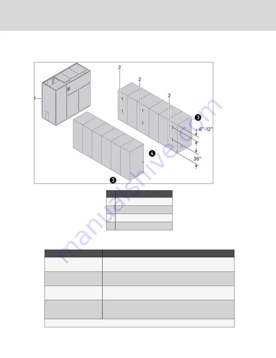
6.2 Location in Data Centers

Figure 6.1 Sensor Locations

Item

Description

1

Liebert thermal management unit

2

Wireless sensor

3

Non-controlled aisle (can be monitored)

4

Controlled aisle

Application

Recommendation

Non-contained aisle control applications

Minimum of two sensors per controlled standard rack face

Each third rack has sensors

Contained aisle control applications

Minimum of two sensors per controlled standard rack face

Each fourth rack has sensors

End racks on rows

Has sensors to detect wrap-around air flow

Racks in between should use guidelines above

Standard rack face

Typical locations are 6" to 12 " from top of rack (depending upon the location of
rack equipment)

Halfway (typically 36")

Additional sensors can be used as needed for more granular control or monitoring.

Table 6.2 Sensor Locations in Data Centers

Vertiv | Vertiv™ Wireless Sensor Network (WSN) Installer/User Guide

20

Summary of Contents for WSN Flex Sensor

Page 1: ...Vertiv Wireless Sensor Network WSN Installer User Guide ...

Page 2: ... and disclaims all liability for damages resulting from use of this information or for any errors or omissions Refer to other local practices or building codes as applicable for the correct methods tools and materials to be used in performing procedures not specifically described in this document The products covered by this instruction manual are manufactured and or sold by Vertiv This document i...

Page 3: ...xiliary Power Cable 15 5 6 Ethernet Connections 15 5 7 Configuring the Gateway 16 5 8 Orienting the Antenna 16 5 9 Resetting to Factory Defaults 17 6 Sensor 19 6 1 Sensor Features 19 6 2 Location in Data Centers 20 6 3 Sensor Mounting Considerations 21 6 4 Sensor Mounting Bracket Kit 21 6 5 Sensor with Expansion Battery Pack and Mounting Bracket Kit 22 6 6 Sensor Startup 23 6 7 Sensor Power Down 2...

Page 4: ...tem 29 7 2 2 Updating the Gateway Firmware 30 8 Product Specifications 33 9 Product Certification and Regulatory Statements 35 9 1 FCC 35 9 2 IC 36 9 3 RF Exposure Warning 36 9 4 RSS Gen 8 4 36 10 Labels and Markings 39 Appendices 41 Appendix A Technical Support and Contacts 41 Appendix B FOSS Compliance 43 Vertiv Vertiv Wireless Sensor Network WSN Installer User Guide ii ...

Page 5: ...is manual thoroughly before attempting to install or operate this unit Only properly trained and qualified personnel should move install or service this equipment Adhere to all warnings cautions installation operating and safety instructions on the unit and within this manual Follow all operating and user instructions WARNING Risk of electric shock Can cause property damage injury or death 1 Safet...

Page 6: ...Vertiv Vertiv Wireless Sensor Network WSN Installer User Guide 2 This page intentionally left blank ...

Page 7: ...e easily and securely added to the gateway using auto discovery programming cables are not required After sensor nodes have been added securely the network can be locked down to prevent unknown devices from entering the network The gateway can support connectivity and communication with up to 300 sensor nodes on a fully populated system For enhanced environmental sensing capabilities WSN FLEX sens...

Page 8: ...Vertiv Vertiv Wireless Sensor Network WSN Installer User Guide 4 This page intentionally left blank ...

Page 9: ... Accelerometer Buzzer sensor 2 AAA Energizer Ultimate Lithium Batteries 1 Sensor Mounting Kit includes Sensor Hook Loop Mounting Plate with Embedded Magnet and Rubber Feet Two 4 Zip Ties Two Wall Mount Screws Two Plastic Wall Anchors Table 3 2 Vertiv WSN Flex Sensor NOTE The Vertiv WSN Flex Sensor can also be powered locally with or without batteries using a micro USB cable not included with order...

Page 10: ... items for visible and concealed damage If damage is noted Report damage immediately to the carrier Send a copy of the filed damage claim to Vertiv or your sales representative IMPORTANT Optional items may be shipped separately or loose These items will be indicated on the packing list Vertiv Vertiv Wireless Sensor Network WSN Installer User Guide 6 ...

Page 11: ...ttings Use the following procedure to change the PC or laptop network settings Refer to Figure 4 1 on the next page 1 Open Windows Control Panel and select Network and Sharing Center 2 Click Change Adapter Settings 3 Right click the Ethernet connection that is being use and select Properties 4 Select Internet Protocol Version 4 TCP IPv4 and click Properties 5 Select Use the following IP address 6 ...

Page 12: ...Figure 4 1 PC or Laptop IP Settings Connecting Port 1 to the Gateway Vertiv Vertiv Wireless Sensor Network WSN Installer User Guide 8 ...

Page 13: ...ding connecting and configuring the gateway See the following figures for illustrations of each of the components Figure 5 1 on the next page Figure 5 2 on the next page Figure 5 3 on page 11 Figure 5 4 on page 11 Figure 5 5 on page 12 Figure 5 7 on page 13 Figure 5 7 on page 13 NOTE Some gateways are used in standalone applications and do not reside on a network In these cases it is still importa...

Page 14: ...Figure 5 1 Gateway and Antenna Figure 5 2 Sensor and Mounting Kit Vertiv Vertiv Wireless Sensor Network WSN Installer User Guide 10 ...

Page 15: ...Figure 5 3 Sensor with Extended Battery Pack and Mounting Kit Figure 5 4 Sensor Mount Top 5 Hardware Installation 11 ...

Page 16: ...Figure 5 5 Sensor Mount Bottom Figure 5 6 Sensor Battery Mount Top Vertiv Vertiv Wireless Sensor Network WSN Installer User Guide 12 ...

Page 17: ... the sensor to gateway communication paths in a parallel alignment to the direction of rack rows as much as possible to reduce perpendicular obstructions to the wireless signal In high density data center environments a maximum diameter of roughly 400 ft with gateway at the center is recommended Open environments and applications with clear line of sight support longer distances The gateway antenn...

Page 18: ...to the host system network process control network and to the wireless field device network The location of the unit must protect the gateway from contamination and moisture 5 3 4 Mounting the Gateway The gateway can be snapped onto a standard 35 mm DIN rail system To clip the unit onto the DIN rail 1 Tilt the unit at a slight angle to allow the lower lip of the chassis to catch the bottom of the ...

Page 19: ...and Powering the Gateway Physically connect the PC or laptop to the gateway with an Ethernet cable and power the gateway using these steps 1 Connect one end to the Ethernet port of the PC or laptop 2 Connect the other end to one of the Ethernet ports on the gateway 3 Connect the locking barrel connector to the gateway using the supplied DC power supply NOTE The auxiliary power cable may also be us...

Page 20: ...ed with an IP address if the network requires an IP address other than the defaults provided in Default Gateway Network Settings on page 7 IMPORTANT Initial access to the gateway must occur using one of the default IP addresses Once the gateway s IP address has been changed communications to the web interface will be lost if it is connected to the port that is being changed If this occurs the PC o...

Page 21: ...ng and holding the reset button for a minimum of 5 seconds The reset button can be accessed beside the antenna using a paper clip Refer to Figure 5 9 below Performing a reset on the gateway only resets the IP addresses on the ports and leaves all other sensor data and system configuration intact Figure 5 9 Antenna Reset Location 5 Hardware Installation 17 ...

Page 22: ...Vertiv Vertiv Wireless Sensor Network WSN Installer User Guide 18 This page intentionally left blank ...

Page 23: ...nsor enclosure with sensor element airflow optimization Configurable sensor polling rates The built in internal batteries provide support for the smaller sensor footprint when frequent data updates are not needed Motion detection using built in accelerometer Wake immediately to transmit Status LED lights Red blue and green are used to indicate user notifications When LED lights are lit individuall...

Page 24: ...ned aisle control applications Minimum of two sensors per controlled standard rack face Each fourth rack has sensors End racks on rows Has sensors to detect wrap around air flow Racks in between should use guidelines above Standard rack face Typical locations are 6 to 12 from top of rack depending upon the location of rack equipment Halfway typically 36 Additional sensors can be used as needed for...

Page 25: ...e attached slide extended battery pack or sensor onto the mounting bracket until it clicks Mounting to ferrous surface Slide the extended battery pack or sensor onto the mounting bracket until it clicks Place the completed assembly onto the metal surface Mounting to a solid wall or surface Use the included screws or anchors as needed to attach the mounting bracket to the surface Once attached slid...

Page 26: ...s and hooks into the expansion battery pack The expansion battery pack then slides and hooks mechanically and electrically into the sensor The expansion battery pack provides supplemental power to the sensor The sensor is powered by two AAA Energizer Ultimate Lithium batteries The expansion battery pack with two AA batteries supplies primary power to the sensor and when the battery voltage drops b...

Page 27: ...tton V emblem on front of sensor is pressed on the front of the sensor the red blue and green LED lights will light together for three seconds During this three second period pressing the main button again turns the red LED on for two seconds and then the sensor enters a deep sleep mode If the main button is not pressed and the three second time period expires the red blue and green LED lights wil...

Page 28: ...arameters may be changed by the user when a sensor is deployed and in active operation Changes in parameters are not remembered across power cycles because non volatile memory is not used in the sensor If a sensor reset cold start is performed or if the batteries are replaced the configurable parameters will revert to the defaults as listed in Table 6 4 below Configurable Parameter Value Sensor Up...

Page 29: ... typically will not have enough capacity to transmit the first payload which happens five seconds after a successful join At this point a short green LED blip will occur as the sensor tries to transmit the first payload but the battery voltage collapses enough to cause the processor to reset If the batteries are extremely low the battery voltage will collapse while the sensor is trying to join the...

Page 30: ...Pins 3 GND and 4 3 3 VDC This can then be used to drive a latching buffer relay Analog Input Mode 0 to 3 0 VDC Analog Input For analog input mode a 0 to 3 0 VDC analog input voltage would be wired to pins 1 or 4 and the ground of the circuit would be wired to pins 2 or 3 respectively Analog Output Mode 0 to 3 0 VDC 8mA Analog Output For analog output mode the analog output voltage of 0 to 3 0 VDC ...

Page 31: ... and date already set The gateway has a real time clock with a battery backup which will retain the time and date for seven years If the time and date need to be reset for any reason use the following procedure IMPORTANT If the gateway is not connected to a host system which can set the date and time using the RESTful API the time and date must be set manually using these procedures NOTE Gateway t...

Page 32: ...g other than the default settings are desired 7 1 2 Reconfiguring a Port To reconfigure a port navigate to the System IP Config page See System IP Config Page below Figure 7 3 System IP Config Page To reconfigure either port enter the new values for the IP Address Subnet Mask and Gateway and click Save If the port configuration is changed for the same port that the PC or laptop is connected to the...

Page 33: ...turn the feature on 3 When the WSNConnect feature is on install the batteries in a sensor or press the V button on the front of the sensor to start the join process 4 The Devices web page will refresh when the gateway detects a new sensor join request Figure 7 4 Sensor and Mount V Button Location Sensors are automatically named using the next sequential number available 7 2 1 Using the Gateway in ...

Page 34: ...start BMS on the System BMS page 2 After the BMS server is restarted The web page will display This site can t be reached The blue status LED on the gateway will turn off The blue status LED on the gateway will illuminate approximately 30 seconds later When the blue status LED on the gateway is illuminated again the BMS server has restarted and is ready for connection again Refreshing the web page...

Page 35: ...re 1 Click Select File 2 Navigate to find and choose the correct firmware zip file provided by Vertiv See 7 2 2 on the previous page NOTE The firmware zip file is an encrypted file and it cannot be unzipped by any Windows utility 3 Select the encrypted zip file and upload 7 Software Setup 31 ...

Page 36: ...Vertiv Vertiv Wireless Sensor Network WSN Installer User Guide 32 This page intentionally left blank ...

Page 37: ... 652g Operating Range Operating temperature 32 F to 140 F 0 C to 60 C RF Characteristics Maximum RF input levels 10 dBm Maximum RF output levels for US CAN AS NZ 27 8 dBm Maximum RF output level for EU 20 dBm Receiver sensitivity 139 dBm at SF12 BW 125 kHz 125 dBm at SF7 BW 125 kHz Frequency range US and Australia 915 ISM Band 902 MHzto 928 MHz Max ERP 24 9mW at 867 1 MHzat 0 C Agency Approvals Ce...

Page 38: ...utton ports on front of sensor Digital Input 3 3VDC Maximum Digital Output 3 3VDC at 8mA Maximum Analog Input 0 to 3 0VDC Measurement Range 3 3VDC Max Analog Output 0 to 3 0VDC at 8mA Maximum Table 8 3 Vertiv WSN FLEX Sensor Specifications Item Specification Power Two AA Energizer L91 Ultimate Lithium Batteries Device Dimensions 83 8 x 43 2 x 55 9 mm 3 3 x 1 7 x 2 2 in With WSN FLEX Sensor Table 8...

Page 39: ... which can be determined by turning the equipment off and on the user is encouraged to try to correct the interference by one or more of the following measures Reorient or locate the receiving antenna Increase the separation between the equipment and receiver Connect the equipment into an outlet on a circuit different from that to which the receiver is connected Consult the dealer or an experience...

Page 40: ...t all times and must not be co located or operating in conjunction with any other antenna or transmitter NOTICE This equipment has been tested and found to comply with the limits for a Class B digital device pursuant to part 15 of the FCC Rules These limits are designed to provide reasonable protection against harmful interference in a residential installation This equipment generates uses and can...

Page 41: ...a applicables aux appareils radio exempts de licence L exploitation est autorisée aux deux conditions suivantes 1 L appareil ne doit pas produire de brouillage 2 L appareil doit accepter tout brouillage radioélectrique subi même si le brouillage est susceptible d en compromettre le fonctionnement 9 Product Certification and Regulatory Statements 37 ...

Page 42: ...Vertiv Vertiv Wireless Sensor Network WSN Installer User Guide 38 This page intentionally left blank ...

Page 43: ...inside of a host product in accordance with Single Module Approved radio rules the following sticker must be permanently placed on the exterior of the host product Figure 10 1 Sticker to be Permanently Placed on Exterior of Host Products 10 Labels and Markings 39 ...

Page 44: ...Vertiv Vertiv Wireless Sensor Network WSN Installer User Guide 40 This page intentionally left blank ...

Page 45: ...patch of technicians for all products 1 800 543 2378 Liebert Thermal Management Products 1 800 543 2778 Liebert Channel Products 1 800 222 5877 AC and DC Power Products 1 800 543 2378 A 2 Locations United States Vertiv Headquarters 1050 Dearborn Drive Columbus OH 43085 USA Europe Via Leonardo Da Vinci 8 Zona Industriale Tognana 35028 Piove Di Sacco PD Italy Asia 7 F Dah Sing Financial Centre 3108 ...

Page 46: ...Vertiv Vertiv Wireless Sensor Network WSN Installer User Guide 42 This page intentionally left blank ...

Page 47: ...de js Development WaveFlex Inc FOSS Statement of Compliance Each npm Module that was used in the WSN Gateway Web UI is stored in the node_modules sub directory along with its License and Copyright information This method of documentation meets the compliance requirements for the open software modules used for development which utilize the MIT License Apache License and ISC License All Node js npm ...

Page 48: ...cense Copyright c 2015 Auth0 Inc support auth0 com http auth0 com Module Name hex2dec 1 1 2 Apache License Version 2 0 January 2004 Module Name jquery 3 4 1 MIT License Copyright JS Foundation and other contributors https js foundation Module Name jsonwebtoken 8 2 2 MIT License Copyright c 2015 Auth0 Inc support auth0 com http auth0 com Module Name jwt MIT License Copyright c 2018 Jason Watmore Mo...

Page 49: ...r damages resulting from use of this information or for any errors or omissions Specifications rebates and other promotional offers are subject to change at Vertiv s sole discretion upon notice Permission is hereby granted free of charge to any person obtaining a copy of this software and associated documentation files the Software to deal in the Software without restriction including without limi...

Page 50: ...power direct or indirect to cause the direction or management of such entity whether by contract or otherwise or ii ownership of fifty percent 50 or more of the outstanding shares or iii beneficial ownership of such entity You or Your shall mean an individual or Legal Entity exercising permissions granted by this License Source form shall mean the preferred form for making modifications including ...

Page 51: ...laim or counterclaim in a lawsuit alleging that the Work or a Contribution incorporated within the Work constitutes direct or contributory patent infringement then any patent licenses granted to You under this License for that Work shall terminate as of the date such litigation is filed 4 Redistribution You may reproduce and distribute copies of the Work or Derivative Works thereof in any medium w...

Page 52: ...or loss of goodwill work stoppage computer failure or malfunction or any and all other commercial damages or losses even if such Contributor has been advised of the possibility of such damages 9 Accepting Warranty or Additional Liability While redistributing the Work or Derivative Works thereof You may choose to offer and charge a fee for acceptance of support warranty indemnity or other liability...

Page 53: ...10 by Internet Systems Consortium Inc ISC Copyright c 1995 2003 by Internet Software Consortium Permission to use copy modify and or distribute this software for any purpose with or without fee is hereby granted provided that the above copyright notice and this permission notice appear in all copies THE SOFTWARE IS PROVIDED AS IS AND ISC DISCLAIMS ALL WARRANTIES WITH REGARD TO THIS SOFTWARE INCLUD...

Page 54: ...Vertiv Vertiv Wireless Sensor Network WSN Installer User Guide 50 This page intentionally left blank ...

Page 55: ...Vertiv Vertiv Wireless Sensor Network WSN Installer User Guide ...

Page 56: ...are trade names trademarks or registered trademarks of their respective owners While every precaution has been taken to ensure accuracy and completeness here Vertiv Group Corp assumes no responsibility and disclaims all liability for damages resulting from use of this information or for any errors or omissions Specifications rebates and other promotional offers are subject to change at Vertiv s so...

Reviews: