background image

2.7 USB Connection

You can connect the Liebert® PSI5 to a computer via USB allowing unattended, controlled shutdown of your computer in
case of UPS input power failure. The UPS works with the computer running software contained in the Microsoft® Windows®
operating system. Use of this feature is not required for proper operation of the UPS. To use this feature, plug the provided
USB cable into USB Type-B port located on the rear panel of the UPS and the other end into an open USB port on your
computer.

2.8 Emergency Power Off (EPO) Connection (Optional)

To comply with national and local wiring codes and regulations, the EPO connector internally disconnects all power sources
to the UPS and connected equipment. The default operation is "active open" which means you must remove the factory-
installed jumper and connect to external contacts that are normally closed but which open during a power-off event. The
logic may be reversed in the Settings; see

Configuring UPS with the Settings Menu

on page 30. If you do not use the

EPO connector, leave the factory-installed jumper in place and the default EPO settings in the Settings.

2.9 External Battery Cabinet Connection on 2U Models (Optional)

External battery cabinets provide longer battery run time for connected devices. Refer to

Specifications

on page 37, and

Run Times

on page 46, to select the appropriate model and quantity for your PSI5 model and applications. You can connect

up to six battery cabinets to the 2U PSI5 models. LI, MT, and 1U models do not support external battery cabinets.

To connect an external battery pack:

1.

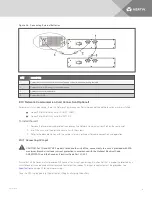
Connect one end of the external battery cable to the UPS and one end to the battery cabinet as shown in
Figure 2.6 on the facing page.

2.

If connecting more than one external battery, connect one end of the external battery cable to the second
connector on the battery cabinet, the connect the other end to the next battery cabinet as shown in Figure 2.6
on the facing page
.

NOTE: After installation and initial startup, set the number of installed battery cabinets in the UPS Settings.

NOTE: When two or more external battery cabinets are used with PSI5-1100/2200/3000/5000 models, the UPS load
rating is decreased by 20%.

Vertiv™ | Liebert® PSI5 Installer/User Guide

20

Summary of Contents for LIEBERT PSI5 MINI-TOWER PSI5-1500MT120

Page 1: ...Liebert PSI5 120V Input 120V Output 208V Input 208V Output Installer User Guide...

Page 2: ...ms all liability for damages resulting from use of this information or for any errors or omissions Refer to other local practices or building codes as applicable for the correct methods tools and mate...

Page 3: ...20 2 8 Emergency Power Off EPO Connection Optional 20 2 9 External Battery Cabinet Connection on 2U Models Optional 20 2 10 Network Communication Card Connection Optional 21 2 10 1 Connecting AC Input...

Page 4: ...4 Maintenance and Battery Replacement 33 4 1 Precautions 33 4 2 Battery Charging 33 4 3 Replacing the UPS Batteries 33 5 Specifications 37 5 1 Run Times 46 Vertiv Liebert PSI5 Installer User Guide 4...

Page 5: ...followed during the installation and maintenance of the UPS and batteries Read this manual thoroughly and the safety and regulatory information available at https www vertiv com ComplianceRegulatoryI...

Page 6: ...Vertiv Liebert PSI5 Installer User Guide 2 This page intentionally left blank...

Page 7: ...y operating time for 2U models The optional Liebert Network Communication Card makes advanced monitoring and control available 1 1 Available Models MODEL FORM FACTOR MODEL NUMBER NOMINAL POWER RATING...

Page 8: ...em Surge Protection Input Output 3 External Battery Connector 4 USB Port 5 Programmable Receptacles 6 Non Programmable Receptacles 7 SNMP IntelliSlot Port 8 Emergency Power Off EPO Connector 9 Input C...

Page 9: ...em Surge Protection Input Output 3 External Battery Connector 4 USB Port 5 Programmable Receptacles 6 Non Programmable Receptacles 7 SNMP IntelliSlot Port 8 Emergency Power Off EPO Connector 9 Input C...

Page 10: ...t Output 3 External Battery Connector 4 USB Port 5 Programmable Receptacles 6 Non Programmable Receptacles 7 SNMP IntelliSlot Port 8 Emergency Power Off EPO Connector 9 Input Circuit Breaker 10 AC Inp...

Page 11: ...em Surge Protection Input Output 3 External Battery Connector 4 USB Port 5 Programmable Receptacles 6 Non Programmable Receptacles 7 SNMP IntelliSlot Port 8 Emergency Power Off EPO Connector 9 Input C...

Page 12: ...ert IntelliSlot Port 2 Input Circuit Breaker 3 AC Input 4 Emergency Power Off EPO Connector 5 USB Port 6 Programmable Receptacles 7 Non Programmable Receptacles Table 1 6 Liebert PSI5 1000 1500RM1201U...

Page 13: ...20 3 Network Phone DSL Surge Protection Connectors 4 Grounding Screw 5 Liebert IntelliSlot Port 6 Non Programmable Receptacles 7 Programmable Receptacles 8 AC Input 9 USB Port 10 AC Input Breaker 11 E...

Page 14: ...Fax Modem Surge Protection Input Output 3 External Battery Connector 4 USB Port 5 SNMP IntelliSlot Port 6 Programmable Receptacles 7 Non Programmable Receptacles 8 Emergency Power Off EPO Connector 9...

Page 15: ...Battery Connector 3 Network Fax Modem Surge Protection Input Output 4 SNMP IntelliSlot Port 5 USB Port 6 Programmable Receptacles 7 Non Programmable Receptacles 8 Output Circuit Breakers 9 Emergency P...

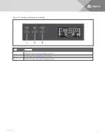
Page 16: ...on page 26 Figure 1 9 Controls and Display on 2U MT and LI Models ITEM DESCRIPTION 1 ON MUTE button See Controls on page 24 for details 2 SELECT button See Controls on page 24 for details 3 OFF ENTER...

Page 17: ...nd Display on 1U Models ITEM DESCRIPTION 1 ON MUTE button See Controls on page 24 for details 2 SELECT button See Controls on page 24 for details 3 OFF ENTER button See Controls on page 24 for details...

Page 18: ...Vertiv Liebert PSI5 Installer User Guide 14 This page intentionally left blank...

Page 19: ...a controlled environment where it cannot be accidentally turned Off The installation environment should meet the conditions listed in Specifications on page 37 Place it in an area of unrestricted airf...

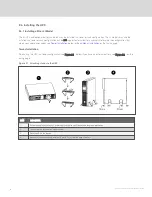
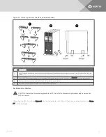
Page 20: ...ack Mount Installation on the facing page Tower Installation When using the UPS in a tower configuration see Figure 2 1 below If you have an external battery see Figure 2 2 on the facing page Figure 2...

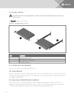
Page 21: ...PS if needed see Figure 2 1 on the previous page 3 Make sure that the stands are installed 70 mm 2 76 in from the edge of the unit 4 Insert the stand expansion components and install the securing scre...

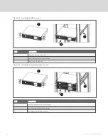
Page 22: ...plied rack kit into the rack 3 Install the UPS in the rack Figure 2 4 Installing the external battery in a rack ITEM DESCRIPTION 1 Attach the brackets to the external battery 2 Install the supplied ra...

Page 23: ...ing Loads The UPS has non programmable and programmable outlets Plug your critical equipment such as computer monitors etc into the non programmable outlets and your less critical equipment such as pr...

Page 24: ...he EPO connector leave the factory installed jumper in place and the default EPO settings in the Settings 2 9 External Battery Cabinet Connection on 2U Models Optional External battery cabinets provid...

Page 25: ...panel 2 Insert the card into the port and secure it with the screws 3 Refer to the documentation with the card or at www Vertiv com for cable connection and operation 2 10 1 Connecting AC Input CAUTIO...

Page 26: ...t the battery is in good condition Vertiv recommends plugging the UPS into AC input and to charge the battery for at least 12 hours prior to providing full backup time protection for any utility power...

Page 27: ...ce is abnormally high The UPS automatically corrects the high voltage and allows the outlets to be On with the normal expected voltage The internal batteries are charging 3 1 5 On Battery Mode The UPS...

Page 28: ...3 1 8 Controls Figure 3 1 Display and Buttons on the front panel of 2U and MT units Figure 3 2 Display and Buttons on the front panel of 1U units Vertiv Liebert PSI5 Installer User Guide 24...

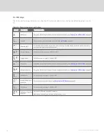
Page 29: ...see Configuring UPS with the Settings Menu on page 30 2 Select Button Select Press to cycle through the operating parameters Settings Menu When in Off mode press and hold for 3 seconds Settings menu D...

Page 30: ...ost mode On AVR Buck mode On Battery mode Estimated backup time in H hours M minutes or S seconds Indicates warning and fault codes See Faults on page 29 and Warnings on page 28 Displays various UPS o...

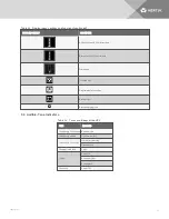
Page 31: ...Table 3 2 Display icons sections and functions continued 3 3 Audible Tone Indicators TYPE INDICATES 1 beep every 10 seconds Battery mode 1 beep every second Overload warning 1 beep every 2 seconds Lo...

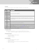
Page 32: ...customer support 1 800 222 5877 Charger failure Call Vertiv customer support 1 800 222 5877 Battery fault Charge the UPS battery for at least 12 hours or replace the battery see Replacing the UPS Bat...

Page 33: ...low 41 Over temperature Make sure that the air temperature is within the range listed in Specifications on page 37 Otherwise call Vertiv customer support 1 800 222 5877 43 Overload Reduce the load to...

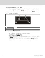
Page 34: ...PS Display in Settings Mode ITEM DESCRIPTION 1 Program option 2 Settings options for selection To access Settings mode and adjust settings 1 Power Off the UPS by pressing the OFF Enter button for at l...

Page 35: ...PSI5 1100 2200 3000 5000 When using two or more external battery cabinets EBCs the UPS load rating will be decreased by 20 The load graph on the LCD automatically adjusts to reflect this derating 08...

Page 36: ...Vertiv Liebert PSI5 Installer User Guide 32 This page intentionally left blank...

Page 37: ...may safely replace the internal battery pack See the Specifications on page 37 for the part number of the replacement battery for your UPS model number NOTE Replace the battery with the same type and...

Page 38: ...the battery box from 2U units to replace batteries ITEM DESCRIPTION 1 Remove the front panel from the UPS 2 Disconnect the battery wires 3 Remove the 2 screws on the front panel of the battery box an...

Page 39: ...left side and remove the 6 screws and the metal battery cover plate 2 Slide out the existing battery kit and disconnect the two halves of the battery connector 3 Orient the connector and the new batte...

Page 40: ...y cover 2 Remove the battery cover 3 Slide out the battery kit and disconnect the battery connector 4 Connect the battery connector to the replacement battery 5 Slide the replacement battery kit into...

Page 41: ...SPECIFICATIONS Table 5 1 on the next page lists the specification for the Liebert PSI5 2U UPS models Table 5 2 on page 41 lists the specification for the PSI5 1U and MT UPS models 5 Specifications 37...

Page 42: ...00W 21 7A 220VAC input 5000 VA 4500W 22 7A 208VAC input 4250 VA 3825W 20 4A 200VAC input 4250 VA 3825W 21 3A Dimensions and Weights Unit Dimensions W x D x H in mm 17 2 x 16 1 x 3 5 438 x 410 x 88 17...

Page 43: ...ter cord 150 mm NEMA L5 30P 3m attached NEMA L6 30P 3 m attached Output Output Voltages on battery 100 110 115 120 125VAC 1 5 on battery before alarm user selectable 120VAC is factory default 200 208...

Page 44: ...n Circuit Breaker Type Valve regulated lead acid VRLA in compliance with UL 1989 Battery Manufacturer Model Leoch DJW12 9 0 CSB HR1234W Quantity x Voltage x Ah 2 x 12V x 9 0Ah 2 x 12V x 9 0Ah 4 x 12V...

Page 45: ...140 23 4 x 27 8 x 5 5 595 x 710 x 140 9 1 x 17 7 x 12 8 230 x 450 x 325 9 1 x 22 4 x 12 8 230 x 570 x 325 Unit Weight lb kg 36 4 16 5 45 6 20 7 24 7 11 2 26 0 11 8 40 1 18 2 Shipping Weight lb kg 40 8...

Page 46: ...ciency 98 96 Buck and Boost Mode Efficiency 93 Recharge Time 6 hours to recover to 90 6 8 hours to recover to 90 Internal Battery Part Number PSI5 10001UBATKIT PSI5 15001UBATKIT PSI5 750MTBATKIT PSI5...

Page 47: ...Input Voltage Input Range with battery operation 0 150VAC Voltage Input Range without battery operation 75 146VAC Input Voltage Measurement Tolerance 3 Nominal Voltage Setting VAC 100 110 115 120 125...

Page 48: ...ing 110 alarm warning and shutdown after 10 seconds 120 alarm warning and immediate shutdown Protection Electronic overcurrent short circuit w latching shutdown AC Mode Efficiency 97 Buck and Boost Mo...

Page 49: ...Battery Manufacturer DLG Quantity x Battery Model 1x LiFe 485000 3x LiFe 722500 Environmental Requirements Operating Temperature F C 32 104 0 40 Operating Elevation ft m 0 9 942 0 3 000 without derati...

Page 50: ...8 239 300 363 40 320 288 21 5 84 155 230 306 384 462 30 240 216 30 5 116 213 313 415 517 620 20 160 144 44 0 167 303 441 581 721 862 10 80 72 85 5 313 552 792 1034 1276 1519 Table 5 4 PSI5 800RT120 LO...

Page 51: ...t PSI5 1500RT120 LOAD NUMBER OF EBCS LOAD NUMBER OF EBCS INTERNAL BATTERY ONLY 1 2 3 4 5 6 VA W MINUTES VA W MINUTES 100 1920 1920 5 0 27 100 1536 1536 72 111 152 194 237 90 1728 1728 6 0 32 90 1382 4...

Page 52: ...613 758 902 10 300 270 103 0 313 10 240 216 653 923 1195 1466 1738 Table 5 8 Liebert PSI5 3000RT120 LOAD NUMBER OF EBCS LOAD NUMBER OF EBCS INTERNAL BATTERY ONLY 1 2 3 4 5 6 VA W MINUTES VA W MINUTES...

Page 53: ...00 360 18 2 30 300 270 26 9 20 200 180 41 9 10 100 90 90 6 Table 5 10 PSI5 1000RM1201U LOAD MINUTES VA W 100 1500 1350 5 1 90 1350 1215 5 9 80 1200 1080 7 1 70 1050 945 8 5 60 900 810 10 6 50 750 675...

Page 54: ...0 23 5 30 225 202 5 33 0 20 150 135 48 0 10 75 67 5 92 5 Table 5 12 PSI5 750MT120 LOAD MINUTES VA W 100 1100 990 4 6 90 990 891 5 6 80 880 792 6 8 70 770 693 8 5 60 660 594 11 0 50 550 495 13 7 40 440...

Page 55: ...600 540 24 2 30 450 405 34 2 20 300 270 50 4 10 150 135 110 9 Table 5 14 PSI5 1500MT120 LOAD MINUTES VA W 100 1500 1350 7 5 90 1350 1215 8 9 80 1200 1080 10 3 70 1050 945 12 1 60 900 810 14 6 50 750...

Page 56: ...8 9 90 2700 2430 10 5 80 2400 2160 11 9 70 2100 1890 13 9 60 1800 1620 16 5 50 1500 1350 20 0 40 1200 1080 25 5 30 900 810 34 2 20 600 540 49 1 10 300 270 96 6 Table 5 16 PSI5 3000RT120LI Vertiv Liebe...

Page 57: ...Vertiv Liebert PSI5 Installer User Guide...

Page 58: ...names and logos referred to are trade names trademarks or registered trademarks of their respective owners While every precaution has been taken to ensure accuracy and completeness herein Vertiv Group...

Reviews: