background image

Vertiv™ |

Liebert® EXM™ UPS 20-100kVA, 50/60Hz User Manual 

|

65

8.4

Detecting Trouble

It is important that the operator check the instrument readings if abnormal equipment performance is 
suspected. Any metered value that differs appreciably from normal could mean an impending malfunction, and 
should be investigated.

Items to check on the various UPS display screens include:

1.

Output voltage of all phases should be within 2% of normal voltage. Output currents on each phase should not normally 
differ by more than 20%. If a greater difference is noted, the load is unbalanced and corrective action should be taken to 
redistribute the load, if possible.

2.

If the UPS has not operated on battery power during the last 10 hours, the batteries should require little charging current. 
Battery mimic should indicate normal DC voltage with relatively little battery charge current.

3.

Input current on each phase should be within 10% of the average input current. Alarm messages indicate malfunction or 
impending malfunction. A daily check of the Operator Control Panel will help to provide an early detection of problems. 
Refer to 

Appendix B

 to interpret alarm messages.

4.

Tracing a problem to a particular section is facilitated by alarm messages and the metered parameter indications. These 
are stored in the Status Reports and can be displayed at the Operator Control Panel or at an optional terminal.

8.5

Reporting a Problem

If a problem occurs within the UPS, review all alarm messages along with other pertinent data. This information 
should be given to the Vertiv

 Services dispatcher. Call 800-543-2378 to report a problem or to request 

assistance.

8.6

Corrective Actions

Recommended corrective actions for each alarm message on the Operator Control Panel and the Remote Alarm 
Status Panel may be found in 

Appendix B - UPS Status Messages

.

8.7

Recommended Test Equipment

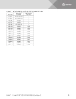
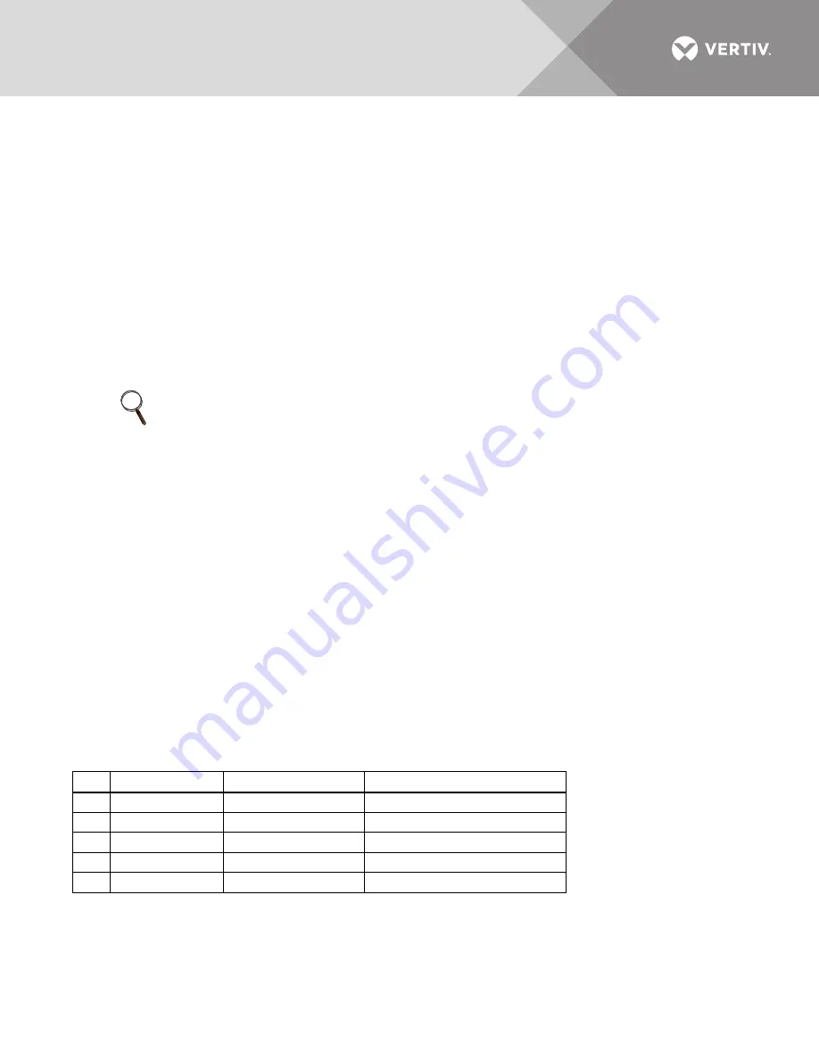
Table 29

 lists recommended test equipment and tools required to maintain, troubleshoot and repair the UPS 

module. Instruments of equivalent range and accuracy may be substituted. All instruments should be calibrated 
and be within the current calibration cycle. Calibration data for the instruments should be maintained in 
equipment-history files and the instruments labeled for audit and verification.

NOTE

If the UPS system has a blown fuse, the cause should be determined before you replace the fuse. Contact 
Liebert

®

 Global Services.

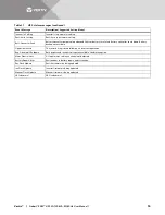
Table 29

Recommended test equipment and tools

Qty

Test Equipment

Manufacturer

Model or Type

1

Oscilloscope

Tektronix, H-P or Fluke

DC to 50 MHz

2

Voltage Probes

Tektronix, H-P or Fluke

10X, with 10 ft. Cable

2

Voltage Probes

Tektronix, H-P or Fluke

100X, with 10 ft. Cable

1

Digital Multi-meter

Fluke

8060, with Test Leads

1

Tool Kit

N/A

Standard electrical contractor tools

Summary of Contents for Liebert EXM

Page 1: ...Liebert EXM UPS User Manual 20kVA to 100kVA 208 120V 50 60Hz...

Page 2: ...damages resulting from use of this information or for any errors or omissions Refer to other local practices or building codes as applicable for the correct methods tools and materials to be used in...

Page 3: ...odule Assembly 13 2 8 Static Bypass Assembly 14 3 0 ELECTRICAL CONNECTIONS UPS 15 3 1 Power Cabling 15 3 1 1 Lug Size and Cable Rating 15 3 2 External Protective Devices 16 3 2 1 Rectifier and Bypass...

Page 4: ...ass 45 6 7 Switching the UPS from Maintenance Bypass to Normal Operation 48 6 8 De Energize Liebert EXM with Maintenance Bypass Cabinet 49 6 9 De Energize Liebert EXM Without Maintenance Bypass Cabine...

Page 5: ...10 Accessory fuses 21 Figure 11 Dual input back feed breaker wiring when bypass distribution cabinet not used 22 Figure 12 Ground and neutral busbar connections 20 100kVA frame busbars 24 Figure 13 S...

Page 6: ...ents and terminals Input for single input unit 208V operation 56 Table 16 UPS currents and terminals Input for dual input unit only 208V operation 56 Table 17 UPS currents and terminals Bypass input f...

Page 7: ...Special safety precautions are required for procedures involving handling installation and maintenance of the UPS system Observe all safety precautions in this manual before handling or installing th...

Page 8: ...levage et l quilibre des armoires avant de transporter l appareil Maintenez en tout temps l inclinaison verticale minimale Les fentes situ es la base des armoires du module sont con ues pour utiliser...

Page 9: ...cause injury property damage and death EARTH CONNECTION IS ESSENTIAL BEFORE CONNECTING THE INPUT SUPPLY Earth leakage current exceeds 3 5 mA and is less than 1000 mA Transient and steady state earth l...

Page 10: ...es La zone entourant le syst me ASC doit tre exempte de flaques d eau d humidit excessive et de d bris Des pr cautions de s curit sp ciales sont requises pour les proc dures associ es la manutention l...

Page 11: ...it generates uses and radiates radio frequency energy and if not installed and used in accordance with this instruction manual may cause harmful interference to radio communications This unit is not d...

Page 12: ...electrical shock Indicates caution followed by important instructions AC input AC output Requests the user to consult the manual Indicates the unit contains a valve regulated lead acid battery Recycl...

Page 13: ...80V or 600V input capability to the Liebert EXM in the optional Liebert BDC Bypass Distribution Cabinet and in the optional Liebert EXM Dual Transformer Cabinet The Liebert EXM provides continuous hig...

Page 14: ...ately 3 Check the product label on the back of front door and confirm the contents match the UPS model capacity and main parameters that were ordered 2 1 1 Storing the UPS and Batteries for Delayed In...

Page 15: ...or blow air down onto the unit The UPS requires 24 in 610mm ventilation clearance above the unit See Table 19 for details on heat dissipation 2 4 Considerations in Moving the Liebert EXM Ensure that t...

Page 16: ...liary terminal blocks and power switches The UPS comes with an Operator Control Panel that provides basic operational status and alarm information The cabinet houses the power components Cooling is pr...

Page 17: ...the equipment point loading Refer to the bottom view in Figure 1 to design this pedestal 2 5 4 Cable Entry Cables can enter the Liebert EXM from the top or bottom through removable metal plates Some...

Page 18: ...ections enabling parallel operation of up to three Liebert EXM UPS in applications offering increased capacity and redundant protection 1 1 2 0 2 1 A partial wraparound maintenance bypass for servicin...

Page 19: ...LED Red Constant Red Auxiliary power failure 15V or 24V rectifier overtemperature rectifier failure including battery SCR short circuit battery converter failure soft start failure main circuit back...

Page 20: ...ly Figure 5 Static Bypass Assembly connections The Static Bypass Assembly has three Liebert IntelliSlot interface card bays and connections for optional ancillary cabinets and for other options Lieber...

Page 21: ...ating according to Table 15 Torque Requirements Refer to Tables 3 and 4 for lug size and torque requirements WARNING Risk of electric shock Can cause property damage injury and death Before connecting...

Page 22: ...evices Any residual current detector RCD installed upstream of the UPS input supply Must be sensitive to DC unidirectional pulses Class A Must be insensitive to transient current pulses and Must have...

Page 23: ...AC input source Vertiv recommends a full capacity neutral conductor and grounding conductors 4 Bypass and rectifier inputs and output cables must be run in separate conduits 5 Control wiring must be r...

Page 24: ...ate conduits 5 Control wiring must be run in separate conduits 6 Optional 54 pole 400A distribution panel or two 225A subfeed breakers 7 Customer must supply a shunt trip breaker with 120V coil If an...

Page 25: ...l Transformer Cabinet is the only approved method for supplying the EXM from two independent sources See SL 25655 for details Both feeds must be protected externally with properly sized protective dev...

Page 26: ...d directly to the UPS itself When this is the case the UPS output cables can be rated to suit the individual distribution network demands rather than being fully load rated When laying power cables do...

Page 27: ...e 11 shows the back feed breaker wiring located on the bypass static switch assembly The Liebert EXM does not include internal back feed protection Shunt trip coils of 120V must be installed in the by...

Page 28: ...eed breaker operation 2 A 120V shunt trip coil is required for proper operation Dual Input Control Wiring Upstream Bypass Input Breaker Upstream System Input Breaker Single Input Control Wiring Backfe...

Page 29: ...cur AVERTISSEMENT Le non respect des proc dures de mise la terre peut entra ner des risques d lectrocution du personnel ou des risques d incendie en cas de d fectuosit de la mise la terre Toutes les o...

Page 30: ...d See 7 3 UPS Electrical Characteristics and Table 20 for recommended breaker ratings Overcurrent protection for the battery circuit must be provided by the customer when using an optional External Ba...

Page 31: ...bypass configuration is used connect the AC input supply cables to the rectifier input terminals A1 B1 C1 N1 and the AC bypass supply cables to the bypass input terminals A2 B2 C2 N1 and tighten the c...

Page 32: ...nmental parameter input interface User communication for data setting and user background monitor Liebert IntelliSlot interface Temperature detect interface Figure 13 Static bypass assembly connection...

Page 33: ...ts Figure 15 Input dry contacts J23 J25 J24 J2 J30 RS232 J1 J19 J20 J21 J22 J26 EPO NO P_MON_CAN_L EPO NC 12V 12V 12V_DRV 12V_DRY ENV_DET GEN_MODE 12V_DRY TMP_BATT TMP_BATT_IN P_SER_BUS_H P_SER_BUS_L...

Page 34: ...GND_DRY Dry Ground 19 MIB_STATUS Maintenance Isolation Breaker Status Open for MIB Closed 21 MBB_STATUS Maintenance Bypass Breaker Status Short for MBB Closed 23 GND_DRY Dry Ground 25 N A 27 UT1_485...

Page 35: ...eed NO 3 Input Backfeed COM 5 Input Backfeed NC J24 2 Input Abnormal NO 4 Input Abnormal COM 6 Input Abnormal NC J25 1 On Battery NO 3 On Battery COM 5 On Battery NC J25 2 Low Battery NC 4 Low Battery...

Page 36: ...d Wire should be 20 16AWG stranded for maximum runs between 80 and 200 feet 25 60m respectively Table 7 Battery cabinet interface J22 Pin Name Description 1 12V_DRV BCB driver signal 3 BCB STATUS BCB...

Page 37: ...d at J2 3 and 4 on the monitor board It also is connected to the Normally Open or Normally Closed remote stop switch between these two terminals using shielded cable see Figure 18 and Table 8 If this...

Page 38: ...iring diagram Field Supplied Wiring Remote Emergency Power Off Customer Supplied Single Liebert EXM Module Liebert EXM Bypass Module 1 2 3 4 EPO_NC EPO_NO 12V 12V X9_J2 J20 J20 J20 J20 J20 EXM14015 Re...

Page 39: ...e unit for air exhaust 36 914mm front access required for service No clearance required in rear except when using seismic anchoring allow 5 127mm clearance 2 Keep cabinet within 15 degrees of vertical...

Page 40: ...0 100kVA unit Replaceable Air Filter Replaceable Air Filter Operator Control Filter Power Modules Bypass Module Input mN Batt N FRONT Door Open RIGHT SIDE Door Open Side Panel Removed Ground Output oN...

Page 41: ...nput C Output Neutral Output A Output B Output C Ground Rectifier Input B Rectifier Input C Batt N Batt Batt Input Neutral 2 5 64mm 4 Places typical 1 9 48mm 6 Places typical 1 8 46mm 1 8 46mm 3 1 79m...

Page 42: ...S UNITY LIFE IS UNITY S IS UNITY DP IS UNITY LIFE This standard card is used for communication between the Liebert EXM and Vertiv s Trellis NMS and LIFE services IS UNITY DP This card can be used inst...

Page 43: ...IS RELAY provides voltage free contact closures for remote monitoring of alarm conditions Delivering On Battery On Bypass Low Battery Summary Alarm UPS Fault and On UPS signals the easy to install ca...

Page 44: ...if battery is OK 4 Common UPS Fault 5 UPS Fault Closed if UPS fault occurs 6 UPS Fault Closed if no UPS failure 7 Common On Battery 8 On Battery Closed if On Battery power Utility failure 9 On Batter...

Page 45: ...commons to be tied together The jumpers should be removed if there is any external voltage source that may intentionally or inadvertently be connected to the relay Removing the shunt from any two pin...

Page 46: ...and out Silencing alarms Turning the UPS On and Off Resetting faults Enabling Energy Saving Mode Scan the QR code at right to obtain a copy of the Touchscreen Control Panel manual WARNING Risk of elec...

Page 47: ...authorized changes to operational settings Can cause equipment damage The default PIN numbers should be changed immediately to prevent unauthorized personnel from changing UPS operation or even shutti...

Page 48: ...the bypass is the preferred source If the bypass voltage or frequency becomes outside preset limits the UPS load is transferred back to the inverter Load on Bypass Mode When the Liebert EXM is operati...

Page 49: ...r by Vertiv Services Power Conditioner Mode When EXM is set to Power Conditioner Mode the battery is disabled in this mode This mode can only be enabled at the factory or by Vertiv Services Maintenanc...

Page 50: ...am transformer Can cause damage to connected equipment If the UPS is supplying a downstream transformer not provided by Liebert the UPS should be put on maintenance bypass to energize it to mitigate t...

Page 51: ...n Bypass Mode with the inverter on standby The status bar at the top of the screen will say ENERGY SAVING MODE ACTIVE 6 5 3 Switching Between UPS Operation Modes To switch from Load on Inverter Mode t...

Page 52: ...t the UPS input refer to Figure 27 For a single source dual input system the bypass isolation breaker BIB can be opened to further isolate the UPS from input power refer to Figure 28 NOTE Pressing Sil...

Page 53: ...l in accordance with national and local electrical codes 2 Input and bypass must share the same single source 3 Vertiv recommends a grounding conductor 4 Bypass and rectifier input and output cables m...

Page 54: ...If those conditions are not present there is a risk of a short interruption in powering the load 1 Verify that the Liebert EXM is operating in Load on Bypass Mode 2 Open the Liebert MBC door to gain...

Page 55: ...capacitors to fully discharge 10 Open the external feeder breaker to the MBC or bypass switchgear 11 Install a Lockout Tagout on the external feeder breaker to the MBC or bypass switchgear 12 Use a di...

Page 56: ...me single source 3 A neutral is required form the system AC input source Vertiv recommends installing a full capacity neutral conductor and grounding conductors 4 Bypass and rectifier inputs and outpu...

Page 57: ...switch gear The system is now de energized and its output power supply is Off 6 11 2 Re Energize a Liebert EXM Parallel System Software Version 1 1 To restart a Liebert EXM parallel system from a ful...

Page 58: ...UPS reaches its end of discharge EOD threshold it will shut down The UPS will automatically restart and enable output power after utility power is restored if Auto Recovery after EOD Enabling is enabl...

Page 59: ...ide of the Operator Control Panel for longer than 2 seconds after the rectifier has qualified After the EPO button is pressed if the input utility is removed the UPS will shut down completely When inp...

Page 60: ...ass supply must be fully synchronized during normal operating conditions This is achieved through the inverter control electronics which make the inverter frequency track that of the static bypass sup...

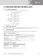
Page 61: ...0 4 5 Criteria B Harmonics IEC 61000 3 4 Electrical Fast Transient IEC 61000 4 4 Criteria B ESD IEC 61000 4 2 Criteria B FCC Part 15 Class A Radiated Immunity IEC 61000 4 3 Criteria A Conducted Immuni...

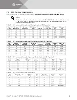
Page 62: ...and terminals Input for dual input unit only 208V operation Unit Rating Nominal Input Current Maximum Input Current OCP Device Rating Bolt Size 75 C Wire Current Total Copper Wire Aluminum Wire 20 59...

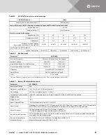
Page 63: ...d THD 5 Full Load Derated operation for reduced input voltage 208V Operation 125 177VAC 220V Operation 132 187VAC Table 21 Battery DC intermediate circuit Parameter 20 100kVA Battery Bus Voltage 288 N...

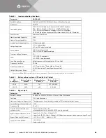
Page 64: ...requency Regulation 0 1 single Liebert Power Module Assembly 0 25 five Liebert Power Module Assemblies Voltage Adjustment Range 5 Factory set to 60Hz 50Hz selectable by commissioning engineer Frequenc...

Page 65: ...Aluminum Two Holes 6AWG 256 030695 868 4AWG 256 030695 733 2 3AWG 54811BE 1AWG 54857BE 1 0AWG 256 30695 593 2 0AWG 54862BE 60238 3 0AWG 54864BE 60244 4 0AWG 54866BE 60250 250kcmil 54868BE 60256 300kc...

Page 66: ...parts except as authorized by Vertiv Maintain the UPS cabinets free of foreign materials such as solder wire cuttings etc Call Vertiv Services if you are not sure of the procedures to follow or if you...

Page 67: ...rge lectrique pouvant entra ner des dommages mat riels des blessures et m me la mort Les op rations d entretien requi rent une extr me prudence Soyez toujours conscient du fait que le syst me ASC cont...

Page 68: ...ERT For customers using Vertiv Services preventive maintenance services periodic inspection of these components is part of this service as well as recommending component replacement intervals to custo...

Page 69: ...odels have replaceable filter elements behind the grille in the front of the unit This element can be changed with the UPS operating by opening the outer door The Liebert EXM s air filters are washabl...

Page 70: ...que values for the connections in the UPS and batteries Use these values unless the equipment is labeled otherwise Table 27 Busbars Power wiring Bolt Shaft Size Lb in Nm 1 2 M12 428 48 Table 28 Termin...

Page 71: ...tored in the Status Reports and can be displayed at the Operator Control Panel or at an optional terminal 8 5 Reporting a Problem If a problem occurs within the UPS review all alarm messages along wit...

Page 72: ...current technical level the following parts still contain hazardous substances due to the lack of reliable substitute or mature solution 1 All solders in the products contain lead 2 Copper alloy conta...

Page 73: ...normal Mains frequency is out of limit range and results in rectifier shutdown Check the rectifier s input voltage frequency Rectifier Fault Rectifier Fault Contact Vertiv Services at 800 543 2378 for...

Page 74: ...assistance Control Power 2 Fail Control Power 2 is abnormal or lost Contact Vertiv Services at 800 543 2378 for assistance Unit Overload The UPS is confirmed to be overload when the load arises above...

Page 75: ...ttery ground fault Battery ground fault from dry contact signal Contact Vertiv Services at 800 543 2378 for assistance Inverter turned On manually Manual Turn On via front panel Inverter turned Off ma...

Page 76: ...d is registered following an incorrect operation Byp Abnormal Shutdown Both bypass and inverter voltages unavailable Load interruption Mains Neutral Lost AC Input mains reference neutral not detected...

Page 77: ......
Page 78: ...and logos referred to are trade names trademarks or registered trademarks of their respective owners While every precaution has been taken to ensure accuracy and completeness herein Vertiv assumes no...

Reviews: