6. For new systems that included an EBC, the EBC communication card should already be
installed in the UPS frame (IntelliSlot Port #3, typically).
•
If it is not installed, obtain the EBC communication card and insert it into any open
IntelliSlot port (preferably Port #3).
•
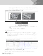
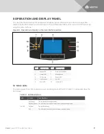
Connect the provided EBC communication cable to the UPS and EBC as shown in Figure
3.25 below or Figure 3.26 on the next page, depending on your system.
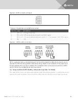
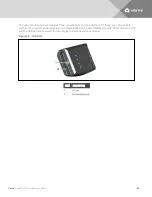
7. Check the EBC DIP-switch settings on the top rear of each EBC frame, and verify that they are
set correctly according to Table 3.12 on page 47.
7. Close the EBC DC circuit breaker and replace the bezels back onto the EBC.
WARNING! Risk of hazardous voltage between UPS frames. Can cause damage to equipment,
injury and death. Failure to open the EBC DC circuit breaker before connecting or
disconnecting the battery cable between the UPS and EBC frames can result in hazardous
voltages being present between the frames.
Figure 3.25 Connecting external battery cabinet to a transformer-free UPS
ITEM
DESCRIPTION
ITEM
DESCRIPTION
1
Liebert APS
4
Battery cable
2
Battery cabinet
5
Ground-wire connection points
3
Communication cable
6
Ground-wire connection points
Vertiv
| Liebert® APS™ Installer/User Guide |
45
Summary of Contents for Liebert APS series
Page 1: ...Liebert APS 5 20 kVA Modular UPS Installer User Guide...
Page 6: ...Vertiv Liebert APS Installer User Guide 6...
Page 10: ...Vertiv Liebert APS Installer User Guide 10 This page intentionally left blank...
Page 50: ...Vertiv Liebert APS Installer User Guide 50 This page intentionally left blank...
Page 76: ...Vertiv Liebert APS Installer User Guide 76 This page intentionally left blank...
Page 80: ...Vertiv Liebert APS Installer User Guide 80 This page intentionally left blank...
Page 109: ......


