C h apter 6 P arallel System A n d L B S System 6 7
L iebert E X S 30 kV A A n d 4 0 kV A U P S U ser M an ual
J3 3.3
EPO
UPS1
EPO
UPS 2
UPS1
UPS 2
J3 3.4
J3 3.3
J3 3.4
J3 3.1
J3 3.2
J3 3.1
J3 3.2
board
Communication
Communication
board
Communication
board
Communication
board
EPO
EPO
UPS
2
UPS
1
UPS
2
UPS
1
J2
2.3
J2
2.4
J2
2.1
J2
2.2
Bypass
module
Bypass
module
J2
2.3
J2
2.4
Bypass
module
J2
2.1
J2
2.2
Bypass
module
J14
14.6
J14
14.8
J14
14.6
J14
14.8
J14
14.2
J14
14.4
J14
14.2
J14
14.4
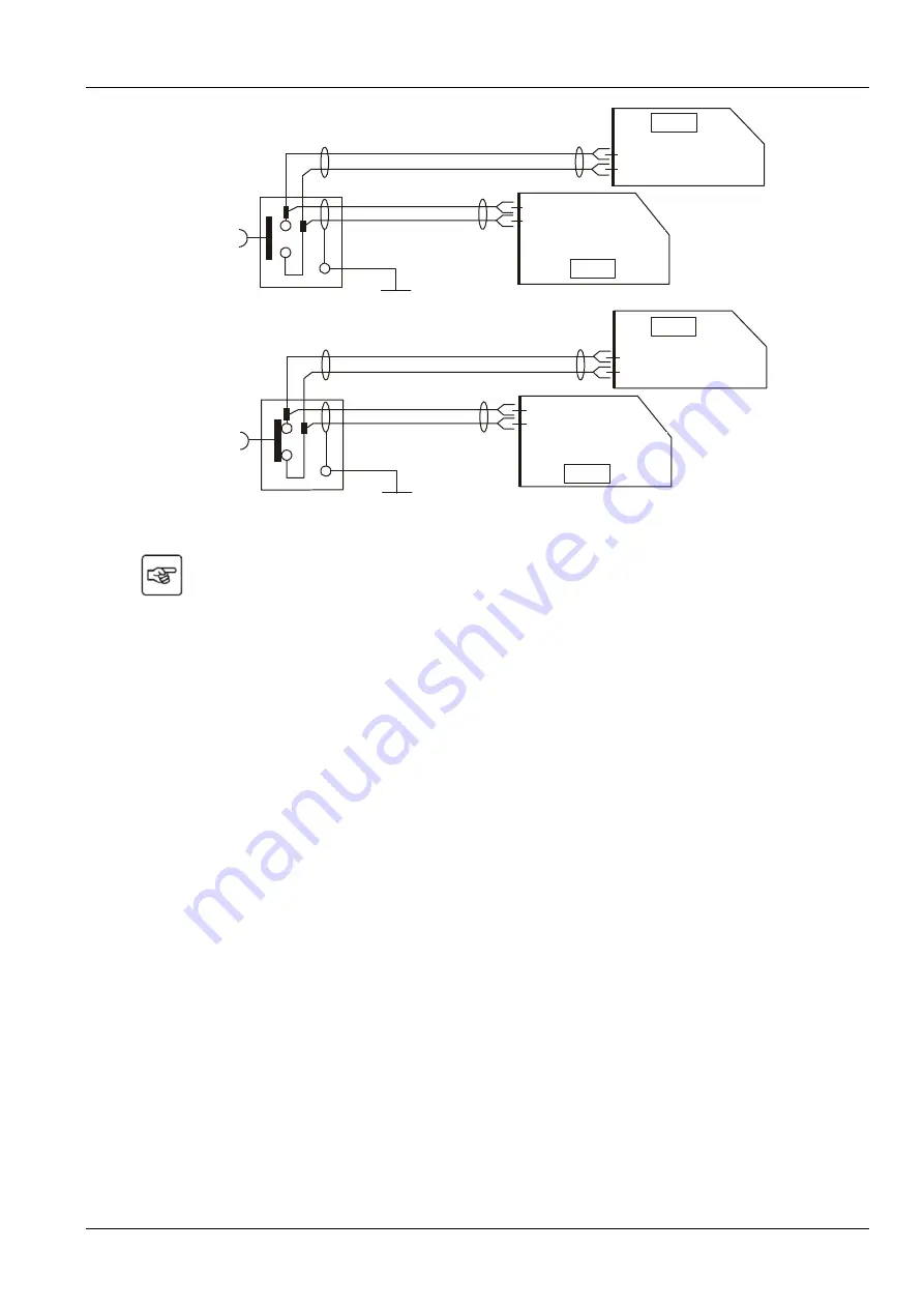
Figure 6 -3 E P O circuit diagram
N o te : In F ig u re 6 -3 , th e u p p e r o n e is N o rm a lly O p e n ty p e , a n d th e lo w e r o n e is N o rm a lly C lo s e d
ty p e .
6 .4
O p eration P roced ures F or P arallel S ystem
6 .4 .1
C heck B efore S tart-u p
1. C heck and confirm that the U P S pow er distribution m ode is correct, that the pow er cables and sig nal
cables are connected correctly, and there are no short circuits.
2. C heck that the batteries have been installed properly, the cables have been connected correctly, and that
the
positive and negative battery poles are correct.
3. C heck all the w orking status of the parallel system , ensure that the phase sequence of the m ain, bypass
and output of each U P S is correct and consistent, that the connection of the parallel cable is reliable, and
that the user load is not connected during pow er-on.
4 . M easure the m ains voltag e and frequency, and verify that they are correct.


