


Interfaces and Connectors
VL-EPICs-36 Reference Manual
36
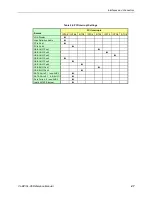
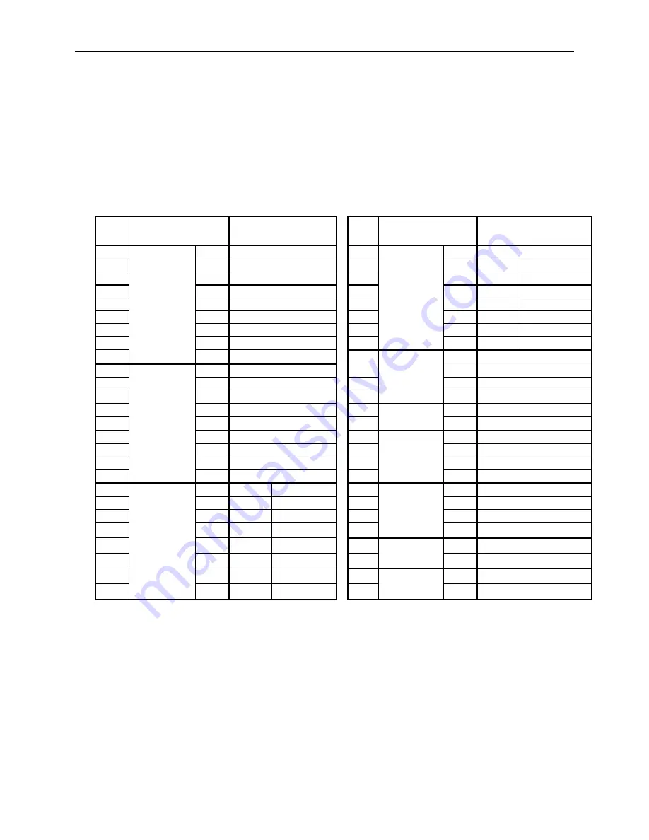
Main I/O Connector (J13)
The 50-pin I/O connector (J13) incorporates the COM ports, PS/2 keyboard and mouse,
programmable LED, reset button, soft power reset, and speaker interfaces. Table 15 illustrates
the function of each pin. The 5.0V power lines provided to J13 are protected by a 1 Amp fuse.
Table 15: I/O Connector Pinout
J13
Pin
VL-CBR-5009
Connector
Pin
Signal
J13
Pin
VL-CBR-5009
Connector
Pin
Signal
1
COM1
1
Data Carrier Detect
COM4
RS-232
RS-232/422/485
2
J3
6
Data Set Ready
26
J5
1
Ground
Ground
3
Top DB9
2
Receive Data
27
5
RTS
TxD+
4
7
Request to Send
28
4
TXD
TxD-
5
3
Transmit Data
29
–
Ground
Ground
6
8
Clear to Send
30
2
RXD
RxD-
7
4
Data Terminal Ready
31
3
CTS
RxD+
8
9
Ring Indicator
32
–
Ground
Ground
9
5
Ground
33
Mouse
4
+5.0V (Protected)
10
COM2
10
Data Carrier Detect
34
J4
1
Mouse Data
11
J3
15
Data Set Ready
35
Top
3
Ground
12
Bottom DB9
11
Receive Data
36
5
Mouse Clock
13
16
Request to Send
37
PBRESET
1
Pushbutton Reset
14
12
Transmit Data
38
S1
2
Ground
15
17
Clear to Send
39
(Reserved)
–
Ground
16
13
Data Terminal Ready
40
–
Not connected
17
18
Ring Indicator
41
–
Ground
18
14
Ground
42
–
Not connected
COM3
RS-232 RS-232/422/485
43
Keyboard
4
+5.0V (Protected)
19
J6
1
Ground
Ground
44
J4
1
Keyboard Data
20
5
RTS
TxD+
45
Bottom
3
Ground
21
4
TXD
TxD-
46
5
Keyboard Clock
22
–
Ground
Ground
47
PLED
1
+5.0V (Protected)
23
2
RXD
RxD-
48
D1
2
Programmable LED
24
3
CTS
RxD+
49
Speaker
1
+5.0V (Protected)
25
–
Ground
Ground
50
SP1
2
Speaker Drive


