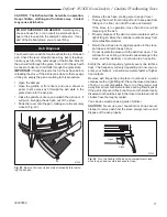
background image

5

Defiant

®

 1975CE Non-Catalytic / Catalytic Woodburning Stove

30005554

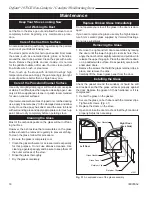
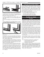
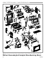
Defiant Noncatalytic/catalytic woodburning Stove


Model 1975ce

(continued)

 item   Description 

part Number


  item Description 

part Number

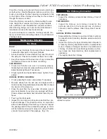
  1.  Brick Support Bracket 

3000579

  .  Griddle Gasket 

103668

  3.  Back 

300054

  4.  Refractory Rt End 

3000506

  5.  Refractory Lt End 

3000507

  6.  Refractory Support 

3000533

  7.  Gasket, Fiber, Refractory Support 

3000537

  8.  Back Insulation Board 

3000569

  9.  Outer Back 

30005485

  9a.  Right Air Deflector 

30005489

  9b.  Left Air Deflector 

30005490

  10.  Left Griddle Quadrant 

3000399

  11.  Right Griddle Quadrant 

3000401

  1.  Griddle 

3000557

  13.  Complete Griddle Handle Assy 

3000775

 13a.  Griddle Handle Wood 

1600661

 13b.  Griddle Handle CRS-BN1 

3000715

 13c.  Nut Hex 1/4-0 

10310

  14.  Griddle Handle Bushing 

101900

  15.  Griddle Handle Bolt 

101308

  16.  Damper Gasket 

103588

  17.  Damper Ramp 

1300643

  18.  Damper Housing 

300081

  19.  Damper

1


3000816

  0.  Damper Tab

1


1601488

  1.  Damper Rod

1


1600065

  3.  Gasket, Fiber Back Refractory 

3000570

  4.  Rheostat Bracket 

3000863

  5.  Refractory, Engine - E/D 

300050

  6.  Damper Handle Screw 

101310

  7.  Damper Handle 

1600644

  8.  Damper Handle w/Screw Assy 

300070

  9.  Left Side  

See Chart Pg. 6

  30.  Left Air Manifold 

3000818

  31.  Right Air Manifold 

3000543

  3.  Right Side 

See Chart Pg. 6

  33.  Thermostat Handle Base Assy 

3000716

  34.  Washer Damper Rod 

10560

  35.  Fireback Plate, S/S 

3000517 

  36.  Inner Bottom 

3000541

  37.  Top Ashdoor Hinge 

3000836

  38.  Door Handle Bracket 

3000844

  39.  Bottom 

3000540

  40.  Ashlip 

See Chart Pg. 6

  41.  Gasket, Fireback 

3000509

  4.  Refractory, Fireback 

3000503

  43.  Retainer, Inner Cover Refractory 

3000548

  44.  Refractory, Inner Cover 

3000505

  45.  Andiron 

300087

  46.  Refractory, Access Cover 

3000504

  47.  Leg Leveller 

101745

  48.  Ashdoor Handle Shaft 

30005301

  49.  Pawl Assy 3/4 short adj 

30005157

 49a.  Spring Washer 

63D0069

  50.  Ashdoor 

3000810

 50a.  Ashdoor Gasket 

103589

  51.  Ashdoor Handle (Wood) 

1600663

  5.  Ashdoor Hinge Rod 

300086

  53.  Cotter Pin, Ashdoor 

30001749

  54.  Ashdoor Bottom Hinge Support 

130064

  55.  Ashpan Bracket 

30001908

  56.  Rear Side Bracket 

3000845

  57.  Thermostat Handle 

1600660

  58.  Airwash Manifold, Frt 

3000544

  59.  Front 

See Chart Pg. 6

  60.  Flue Collar Gasket 

30004

  61.  Left Door 

See Chart Pg. 6

  6.  Door Hinge Strip 

1300645

  63.  Top 

See Chart Pg. 6

  64.  Glass Clip 

30001715

  65.  Glass Clip (Right Door Only) 

30001716

  66.  Front Door Handle & Shaft 

3000717

  67.  Right Door 

See Chart Pg. 6

  68.  Door Gasket 

7000910

  69.  Glass Gasket 

103556

  70.  Left Door Glass 

3000547

  71.  Right Door Glass 

3000547

  7.  Lower Door Hinge Pin 

300077

  73.  Spacer (for Damper rod) 

101779

  74.  Upper Door Hinge Pin 

300077

  75.  Complete Handle Assy 

30004175 

 75a.  Handle Base Stub 

3000714

  76.  Wood Handle 

1600664

  77.  Handle Bolt 

101310

  78.  Thermostat Handle Bolt 

10143

  79.  Ash Pan Assy 

30001690

  80.  Flue Collar 

See Chart Pg. 6

  81.  Leg 

See Chart Pg. 6

  8.  Hex Head Jam Nut 

10390

  83.  Bottom Heat Shield 

30005037

 83a.  Bottom Heat Shield Rt Wing 

30005038

 83b.  Bottom Heat Shield Lt Wing 

30005039

  84.  Grate Bottom 

3000534

  85.  Thermostat Assy. 

5005470

  86.  Thermostat Cable 

5005471

  87.  Thermostat Friction Spring 

101846

  88.  Primary Air Valve Assy. 

3000575

  89.  Heat Plate Vertical Flue 

3000565

  90.  Catalyst, Ceramic 

30005353

Summary of Contents for 1975CE CE

Page 1: ...ined a house fire may result To reduce the risk of fire follow the installation instructions Failure to follow instructions may result in property damage bodily injury or even death Contact local buil...

Page 2: ...Vermont Castings stove has been made with the utmost care and will provide you with many years of service As you become acquainted with your new stove you will find that its appearance is matched by...

Page 3: ...missions 13 O2 Catalyst 08 noncat 48 Loading Front and top Chimney connector for 8 flue collar 203 mm 8 diameter for 6 flue collar 152 mm 6 diameter Chimney flue size for 8 flue collar 203 mm 8 minimu...

Page 4: ...house fire Followallinstructions exactly and do not allow makeshift compromises to endanger property and personal safety all local regulations including those referring to na tional and European stan...

Page 5: ...masonry chimney with a nominal flue size of 203 x 203 mm 8 x 8 or 203 x 305 mm 8 x 12 and into a round flue with nominal flue size of 203 mm 8 A Defiant with a 152 mm 6 flue collar is approved for ve...

Page 6: ...efiant is equipped with the 203 mm 8 flue collar an oval to round adapter will be needed Double wall oval to round adapters are available from some manufacturers Your local dealer can help you select...

Page 7: ...ney connector to the outer end of the sleeve with sheet metal screws ST243 thinble connection 12 13 99 djt Thimble Sleeve Chimney Connector Flue Keep sleeve end flush with flue tile ST243 Fig 6 The th...

Page 8: ...through in your installation check with your building inspector before you begin Also check with the chimney connector manufacturer for any specific requirements Accessories are available for use as...

Page 9: ...ve and its connector and nearby combustibles Clearance is the distance between either your stove mea sured from the bottom edge of the stove s top plate or chimney connector and nearby walls floors th...

Page 10: ...nry other than to allow safe access to the controls of the stove For this reason minimum side clearances of 125 mm and a minimum rear clearance of 50 mm are recommended Summary of Clearances Minimum r...

Page 11: ...t Shield Elevation With Shield a t l e a s t 3 x D at least 1 5 x D at least 1 5 x D Plan Without Shield Plan With Shield Air space of at least 12 mm between noncombustible shield and combustible mate...

Page 12: ...ar of the stove The unpainted side must face up towards the stove 3 Pass all four bolts through the large end of the keyholes and then pulling the shield forward to engage the smaller ends of the keyh...

Page 13: ...Installation 1 Attach the fan assembly at the bottom edge of the in ner back with two 2 1 4 20 x 3 4 hex head screws 2 Attach snapstat to the mounting holes on the underside of the bottom with two 2 1...

Page 14: ...e inner cover by pulling it straight out Fig 22 3 Remove the catalyst by gently pulling it straight out Fig 23 Place the catalyst where the catalyst s ce ramic components will not be damaged ST1187 re...

Page 15: ...atic thermostat to ensure an even heat output at whatever manual setting you select The thermostat senses the heating and cooling of the stove surface and adjusts the air shutter accordingly A Damper...

Page 16: ...king or the fire may go out if the fire dies down immediately as a result of the damper being closed Once the combustor starts working heat generated by burning the smoke will keep it working To deter...

Page 17: ...e the ash pan making sure to keep it level To keep the cover from sliding off and to keep ash from falling on the floor do not tilt the ash pan forward If the stove is in operation close the ash door...

Page 18: ...ue that accumulates on the glass surface should be removed regularly to prevent etching To clean the glass follow this procedure Be sure the glass is completely cool Clean the glass with water or a cl...

Page 19: ...spot Continuetomake small adjustments until the setting is right If additional adjusting of the latch does not enable the door to seal sufficiently in one area try adjusting the gasket in that area Pa...

Page 20: ...nless the involved parts are disassembled and then put back together If this is the case the job should be done only by a qualified service technician 5 16 diameter gasket seals the following parts Th...

Page 21: ...and replace if necessary Remove ashes from the ash pan and replace with a moisture absorbing material such as kitty litter to keep the interior of the stove dry Clean the dust from the inner sides of...

Page 22: ...ot If this test indicates a problem consider other possible fac tors as well such as the weather or a change in the quality of your fuel In warm weather draft is weaker than it is in colder winter wea...

Page 23: ...as fast it is likely that the performance change was caused by fly ash deposits on the catalytic element However continue the inspections of the chimney system for a few weeks to ensure that proper pe...

Page 24: ...Defiant Noncatalytic Catalytic Woodburning Stove 9 80 21 20 17 19 16 18 10 11 2 13a 14 15 13b 63 58 32 59 3 36 29 81 39 40 47 38 12 45 37 31 50 51 52 55 70 69 64 68 62 74 72 61 71 69 65 67 74 72 62 30...

Page 25: ...Ashlip See Chart Pg 26 41 Gasket Fireback 30005209 42 Refractory Fireback 30005203 43 Retainer Inner Cover Refractory 30005248 44 Refractory Inner Cover 30005205 45 Andiron 30002827 46 Refractory Acce...

Page 26: ...the firebox should be replaced with stainless steel for ease of future disassembly Defiant Noncatalytic Catalytic Woodburning Stove Model 1975CE continued Shell Enamel Parts Defiant Model 1975 Brown P...

Page 27: ...2 Proof of original purchase date 3 Date of failure of catalyst 4 Any relevant information or circumstances regarding determina tion of failure 5 In addition the owner must return the failed catalyst...

Page 28: ...MHSC 149 Cleveland Drive Paris Kentucky 40361 www mhsc com...

Reviews: