


1
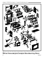
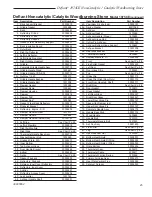
Defiant
®
1975CE Non-Catalytic / Catalytic Woodburning Stove
30005554
assembly
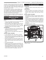
Set Up your Stove
Cast iron stoves are heavy, and it will take two to four people
to move your Defiant into position.
Wipe the protective
coating of oil from the
griddle with a clean
dry rag or a paper
towel.
Install the handle on
the griddle. First,
place the griddle up-
side down at the edge
of a flat surface and
assemble the handle as shown.
With the handle pointing 45° from its final position, tighten
the nut as far as possible with the pliers. Move the handle to
its final position while still holding the nut with the pliers.
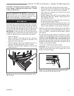
Storing the handle
Use the removable handle to open or close the doors. After
using it, remove the handle so it will not get hot. Store the
handle in the handle holder installed behind the right front
leg. (Fig. 15)
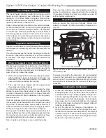
ST516
Attach
griddle handle
11/17/00 djt
ST516
Fig. 14
Attach the griddle handle.
ST564
handle holder
12/13/00
Bottom Heat Shield
Door Handle Holder
Leg Bolt and Washer
ST564
Fig. 15
Handle holder and heat shield positions.
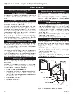
install the bottom heat Shield
NoTe:
The Bottom Heat Shield is required in most in-
stallations. Refer to Floor Protection, Page 9, for further
details.
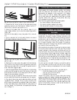
1. Loosen the four 1/4-0 hex head bolts from the corners
of the ash drop on the stove bottom.
. Align the bottom heat shield holes with the four bolts.
The outside air cutout hole should be toward the rear
of the stove. The unpainted side must face up towards
the stove.
3. Pass all four bolts through the large end of the keyholes
and then pulling the shield forward to engage the smaller
ends of the keyhole slots. (Fig. 16)
4. Attach the heat shield sides by passing the slots over
the bolt heads. Tighten the hex head bolts.
ST857
abottom heat shield
12/05
1/10
ST857a
Fig. 16
Attach the bottom heat shield.
Bottom Heat Shield
adjust the leg levellers
Lift the stove slightly so there is no weight on the leg
while making the adjustment.
Reverse the Flue collar (if necessary)
Reverse the flue collar by removing the two screws that
attach it to the back of the stove. Be sure the gasket around
the flue collar opening is in position when you screw the
collar back onto the stove.
adjust air Deflector
If you have the optional fan kit, you may decide to adjust the
air deflector to blow heat across the top of your stove. (Fig.
17) Loosen the two () screws on each side and raise or
lower the deflector. After adjustment, tighten the screws.
attach Flue collar heat Shield
waRNiNg:
The flue collar heat shield must be attached
to the Defiant stove. Use four #10 sheet metal screws
supplied to secure the flue collar heat shield to the rear of
the stove. (Fig. 17)
attach the Damper handle
Use the 1/4” -0 x 3” screw to attach the damper handle
to the damper stub on the left side.
attach the primary air Thermostat handle
The primary air thermostat handle is the smaller of the
two black handles. Secure the handle to the stub on the
right side of the stove with an 8-3 x ” slot head machine
screw. (Fig. 18)


