Verizon Networkfleet 5200, Installation Manual
The Verizon Networkfleet 5200 is a cutting-edge fleet tracking system designed to optimize vehicle management. Ensure seamless installation with our comprehensive Installation Manual, available for free download from our website. Stay informed, maximize efficiency, and streamline operations with this user-friendly manual.
Share
Download


Reviews:
No comments
Related manuals for Networkfleet 5200

Eagle View
Brand: Eagle Pages: 24

EM-406
Brand: Globalsat Pages: 9

GPSMAP 176C
Brand: Garmin Pages: 16
Tracker 5507
Brand: Navman Pages: 79

GPSMAP 695
Brand: Garmin Pages: 210

GPSMAP 76Cx
Brand: Garmin Pages: 102

GPSMAP 60Cx
Brand: Garmin Pages: 100

GPSMAP 60CSx
Brand: Garmin Pages: 116

GPSMAP 76C
Brand: Garmin Pages: 96

WristableGPS SS-300
Brand: Epson Pages: 142

SS-500R
Brand: Epson Pages: 144

SS-300B
Brand: Epson Pages: 142

TwoNav Ultra 2.6
Brand: CompeGPS Pages: 50

MARKER 1
Brand: QUALISYS Pages: 2

KL-P103
Brand: Konlen Pages: 17
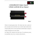
GPS103-A
Brand: Coban Pages: 19
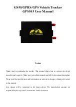
GPS105
Brand: Coban Pages: 24

Yepzon Coco
Brand: PackAware Pages: 2


