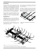
background image

1

1

/

4

"

2

1

/

8

"

Figure 11: Mounting screw hole depth.

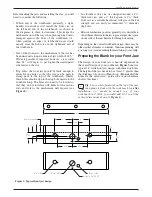
Install the #14 fl at-head screws to secure the front plate 
to the front jaw.

#14 × 2

"

Flat-Head 

Wood Screws

Figure 12: Attaching front plate to front jaw.

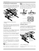
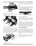
Remove the clamps holding the jaw to the apron. Flip 
the workbench upright (or reinstall the workbench 
top on its base). Insert the handle into the tee, slide 
an O-ring onto each end of the handle, then attach the 
end caps with the #8 screws, as shown in 

Figure 13

(The O-rings will protect the end caps from banging 
into the tee as the handle is rotated.)

#8 × 1

1

/

2

"

Flat-Head 

Wood Screw

Handle 
End Cap

O-Ring

Handle

Figure 13: Installing the handle.

Plane the top of the jaw so that it is fl ush with the top 
of the workbench. Apply the desired fi nish to the jaw.

Use

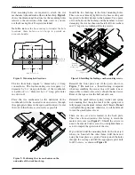
A novel feature of this vise is the quick-release half nut. 
To actuate, fl ip the quick-release lever from horizontal 
to vertical, as shown in 

Figure 14

. (You may need to 

rotate the handle to release the threads.) 

Cam lever in engaged position.

Rotate cam lever to "up" position 
to release main screw. 

Figure 14: Releasing the half nut.

Caution: Do not


release the half nut when the vise 

is loaded. Disengaging a loaded vise will result in 

sudden release of clamping pressure, which can lead to 
damage of the vise and workpiece, as well as injury to 
the user.

To re-engage the half nut, simply fl ip the lever back to 
horizontal. If the threads in the half nut are not aligned 
with those on the main screw, the lever may not return 
immediately to horizontal. If this is the case, you can align 
the threads by rotating the main screw; this will, in turn, 
force the quick-release spring to nudge the half nut into 
place, and snap the quick-release lever to horizontal.

Care and Maintenance

The vise comes fully lubricated; however, it will need 
periodic cleaning and lubrication. White grease on the 
main screw will ensure smooth operation, and a light 
oiling of the half nut will keep this component moving 
freely. The guide rods do not require lubrication; they 
have a surface treatment that is self-lubricating and 
prevents rust.

Note:


Do not

 use silicone-based lubricants on the 

main screw. The main screw has a special hardening 
treatment and surface coating that is not compatible 
with silicone-based lubricants.

7

Veritas

®

 Quick-Release Front Vise

Summary of Contents for 05G34.01

Page 1: ...U S Des Pat No D673 830 05G34 01 Quick Release Front Vise ...

Page 2: ...h ease of installation as a primary requirement the instructions offer critical information to facilitate the task These instructions assume the workbench has a 2 thick apron Please refer to Appendix 1 for installation on a workbench with no apron These instructions show an installation on the left end of the workbench which would be typical for a right handed woodworker Assuming a 13 4 thick fron...

Page 3: ... around a 13 4 thick front jaw and a 2 thick apron A 13 4 thick front jaw in a suitable hardwood will give sufficient strength and can easily accommodate 3 4 diameter dog holes Relative mechanism position generally it is desirable to offset the mechanism in the jaw to give a larger clear space on one side of the mechanism for through clamping Depending on the overall workbench design there may be ...

Page 4: ...are installing a softwood jaw Tip It may be easier to drill the holes for the mounting screws later in the installation process Note A drill press is recommended for boring these holes to ensure they are bored square to the jaw face Tip When drilling the holes for the main screw guiderods etc donotrotateorturntheworkpiece on the drill press table See Figure 5 Instead slide the workpiece over If yo...

Page 5: ...guide rod screws and carefully pull the front plate off The fit between guide rods and front plate is tight you may need to progressively tap each side until these come apart Avoid skewing the front plate in relation to the guide rods Fromthispointon theinstallationofthevisemechanism will be much easier if the workbench is flipped upside down Alternatively if your workbench top is easily removable...

Page 6: ...oid damaging the vise mechanism Install all four washers and 3 8 lag screws tighten all the lag screws Figure 10 Installing the bushings washers and lag screws Reinstall the front plate and all the parts shown in Figure 7 Do not use a thread locking compound when reassembling the vise as this will make it near impossible to remove the screws should the need arise Remove the tape across the half nu...

Page 7: ...main screw Figure 14 Releasing the half nut Caution Do not release the half nut when the vise is loaded Disengaging a loaded vise will result in sudden release of clamping pressure which can lead to damage of the vise and workpiece as well as injury to the user To re engage the half nut simply flip the lever back to horizontal If the threads in the half nut are not aligned with those on the main s...

Page 8: ...s been installed Attach the rear jaw to the workbench with lag screws or other attachment method Clamp the drilled front jaw in place as shown in Figure 6 and follow the rest of the instructions for installing the vise mechanism as though the workbench had an apron Figure 17 Assembly with rear jaw Appendix 2 Cam Orientation If for some reason the vise mechanism is disassembled beyond the point des...

Reviews: