


6%2)3).$5342)%3
H8186-CB
INSTALLATION GUIDE
Z204062-0E
page 5
©2008 Veris Industries USA 800.354.8556 or 503.598.4564 / [email protected]
06081
Before beginning this procedure, set the wiring, baud rate, and parity using the
Communication DIP switches, and set the network address using the Network
Address DIP switches (see the Configuration section on page 2 of this installation
guide).
1. Turn off all power to the energy meter and the equipment in which it is
installed:
a. Remove the voltage terminal from the energy meter
and all fuses.
b. Always use a properly rated voltage sensing device to
confirm that power is off.
2. To discharge static, follow the instructions that come with your
anti-static or grounding strap.
NOTE: Use an anti-static or grounding
strap at all times during installation.
3. Slide the H8186-CB into the slot in the energy meter. The sides of the H8186-CB
slide down into the channels on either side of the energy meter. When the male
connection to the energy meter (see below) clicks into place, the H8186-CB is
properly installed.
troubleshooting
CAUTION: ESD-SENSITIVE COMPONENTS
Use an anti-static or grounding strap (customer-supplied) to ground yourself and
discharge any static charge before installing the H8163-CB. Static can damage
electrostatic discharge-sensitive components in the circuit monitor and its
accessories. Failure to follow this instruction can result in equipment damage.
SLOTS
TOP
COMMS BOARD
BATTERY
CONNECTORS
CONNECTION
SLOTS
4. Insert the communication terminal onto the RS-485 communication
terminals.
5. If the demand subinterval feature is used, wire into the end of the demand
subinterval terminal.
6. Replace the voltage terminal into the energy meter.
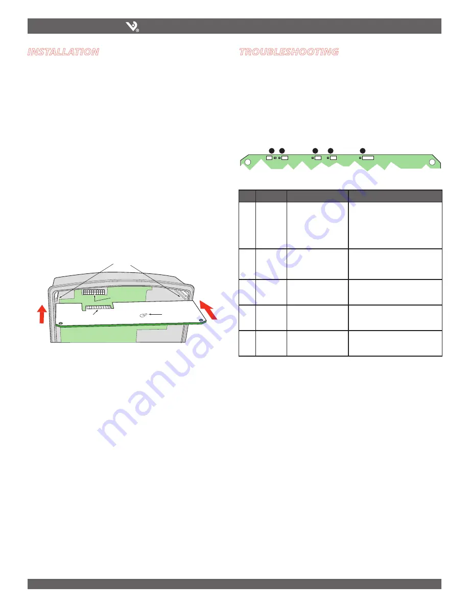
There are five LEDs that indicate various types of communication. The figure below
indicates the locations of these LEDs. All LEDs will blink when operating normally.
If there is a problem communicating, first be sure that the board is properly seated
in its slot on the energy meter. Verify that the sides of the H8186-CB are in the slots
on the sides of the energy meter and that the connector has clicked into place in the
connection slot of the energy meter. If all these factors are normal, see the table
below to interpret the LED blink codes.
ON
1 2 3 4 5 6
ON
1
2 3 4 5 6
1
2
TX
RX
3
RX
4
TX
5
6
7
8
9
10
ALIVE
D5
D6
D13
D14
D1
LED
Abnormal Operation
Solution
1
RS-485 LED
(TX)
Not Blinking
There is no communication from the
H8163 to the master. Check the wiring;
TX+/TX- and RX+/RX- may be reversed.
Correct the wiring. If RX is blinking,
verify the DIP switch address, parity,
baud rate, and wire type.
2
RS-485
(RX)
Not Blinking
There is no communication from the
master. The RX+ and RX- wires are
reversed. Correct the wiring.
3
From main
board
(RX)
Not blinking
The main board is not responding.
Contact the factory for support.
4
From main
board
(TX)
Not blinking but “Alive”
LED is blinking
There is an internal communications
board error. Contact the factory.
5
“Alive”
status
Steadily lit
There is an internal communications
board error. Contact the factory for
support.
LED positions on the EMCB
installation
Archived Document


