background image

4.  Ensure that the end of line (EOL) switch is set to the off position.
5.  Use the zone bus address range 4-127 for Verasys zone bus controllers.
6.  Place the ZEC510 on the actuator shaft so that the wiring connections are easily accessible.
7.  Ensure that the ZEC510 base is parallel to the VAV box, perpendicular to the damper shaft. If

necessary, use a spacer to offset tipping of the ZEC510 caused by the shaft bushings.
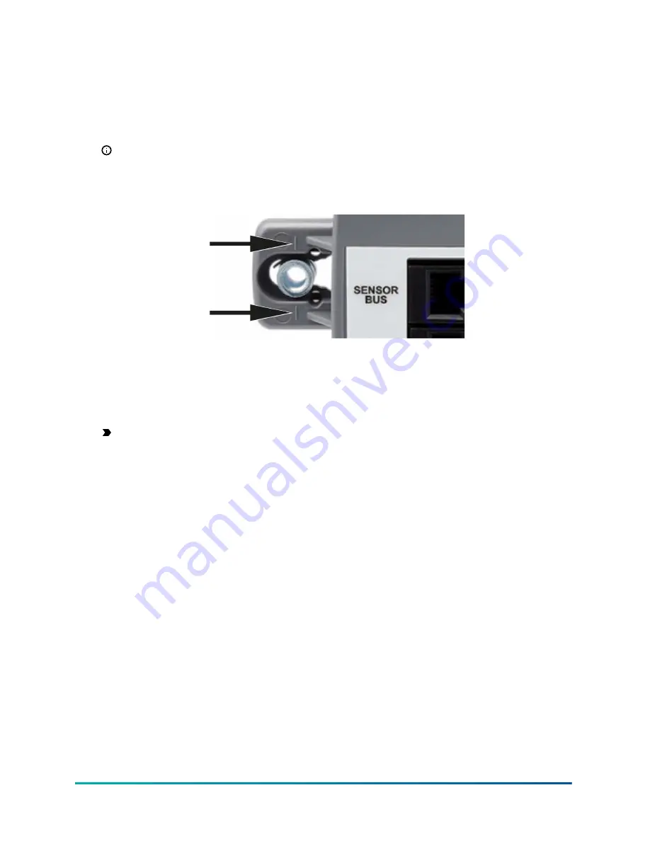
Note: 

Use the alignment marks to center the captive spacer to ensure sufficient

movement in either direction.

Figure 1:  Captive spacer alignment marks

8.  Secure the self-drilling no.10 screw through the captive spacer with a power screwdriver

and 100 mm (4 in.) extension socket. Alternatively, use a punch to mark the position of the

shoulder washer.

9.  Drill a hole into the VAV box using a 5/16 in. drill bit.
10.  Insert the mounting screw and tighten it against the spacer.

Important: 

Do not over-tighten the screw. Over-tightening can cause the threads to strip.

If you mount the ZEC to the VAV box, make sure that the screws do not interfere with

damper blade movement.

11.  Locate the damper position using the marking on the end of the damper shaft.
12.  Note the direction, clockwise (CW) or counterclockwise (CCW), required to close the damper.

The actuator configuration depends on the amount of rotation necessary for the damper to go

from the full-open to the full-closed position. Decide between the following options:

- For 90° rotation, install the damper in the full-closed position.
- For 45° or 60° rotation, install the damper in the full-open position.

13.  Push down and hold the manual override button and turn the actuator coupler until it contacts

the mechanical end-stop at either the full-closed or full-open position.

7

Verasys ZEC510 VAV Controllers Installation Guide

Summary of Contents for ZEC510

Page 1: ...barcode for factory use only LC ZEC510 3 Building Technologies Solutions www johnsoncontrols com 2021 04 08 241014301485B Verasys ZEC510 VAV Controllers Installation Guide Part No 24 10143 01485 Rev B...

Page 2: ...2 Verasys ZEC510 VAV Controllers Installation Guide...

Page 3: ...17 ZEC510 terminal functions ratings requirements and wiring guidelines 19 Input and output wiring guidelines 19 System and zone bus supply power wiring guidelines 19 Sequence of operation 24 Occupie...

Page 4: ...th American emissions compliance 31 United States 31 Canada 32 Product warranty 32 Software terms 32 Single point of contact 32 Contact information 33 Verasys ZEC510 VAV Controllers Installation Guide...

Page 5: ...VAV controller Important Utiliser ce ZEC510 VAV controller uniquement en tant que dispositif de contr le de fonctionnement Lorsqu une d faillance ou un dysfonctionnement du controller risque de provo...

Page 6: ...he top bottom sides and front of the controller for cable and wire connections and adequate ventilation through the controller Do not mount the ZEC510 in areas where electromagnetic emissions from oth...

Page 7: ...box using a 5 16 in drill bit 10 Insert the mounting screw and tighten it against the spacer Important Do not over tighten the screw Over tightening can cause the threads to strip If you mount the ZE...

Page 8: ...r 45 and 60 boxes The closed damper seal provides the full closed stop 15 Tighten the square coupler bolt to the shaft using an 8 mm 5 16 in wrench or 10 mm 3 8 in 12 point socket Tighten to 10 5 N m...

Page 9: ...nly Make all wiring in accordance with local national and regional regulations To wire the ZEC510 complete the following steps 1 Use the appropriate figures according to your particular configuration...

Page 10: ...ensor bus 2 Sensor bus terminal block plug on the terminating device 3 Daisy chained device on a sensor bus segment 4 Sensor bus terminal block plug on the daisy chained device 5 Cable shield connecti...

Page 11: ...d device 5 Cable shield connection 6 Connects to the next device on the zone bus Connects to all ZECs and the zoning roof top unit RTU of the VZC100 Modular ports The modular sensor and zone bus ports...

Page 12: ...ts into a board mounted jack on the upper left of the ZEC controller Wire the 24 VAC supply power wires from the transformer to the HOT and COM terminals on the terminal plug as shown in the following...

Page 13: ...ise interference and ground loop problems You may damage the controller by sharing power with other devices Wiring diagrams ZEC510 1 controller VAV with staged reheat control wiring example Figure 9 Z...

Page 14: ...eutral occupancy switch OCCUPANCY STATUS IN2 OCC S Dry Contact Normally Open Normally Closed is configurable through the interface 15 Optional Discharge air temperature sensor TE 631GV 2 DISCHARGE AIR...

Page 15: ...ZEC510 2 controller VAV with incremental reheat control wiring example Figure 11 ZEC510 2 flow diagrams Figure 12 ZEC510 2 wiring diagram 15 Verasys ZEC510 VAV Controllers Installation Guide...

Page 16: ...y switch OCCUPANCY STATUS IN2 OCC S Dry Contact Normally Open Normally Closed is configurable through the interface 13 Optional Discharge air temperature sensor TE 631GV 2 DISCHARGE AIR TEMPERATURE IN...

Page 17: ...Figure 13 Piping details ZEC510 3 controller Multizone unit VAV with proportional reheat control wiring example Figure 14 ZEC510 3 Flow diagrams 17 Verasys ZEC510 VAV Controllers Installation Guide...

Page 18: ...OUTPUT OUT4 HTG O 0 VDC to 10 VDC 6 Optional Heating stage command HEATING STAGE COMMAND OUT5 HTG C 24 VAC on off externally sourced 7 Pressure ports No polarity 8 Manual override n a 9 Optional Suppl...

Page 19: ...resses in the Configuring the NS sensors section The fifth sensor must have the fixed address 199 If you install CO2 Net sensors in addition to the 24 VAC power for the controller you must also supply...

Page 20: ...ts OCOM2 to 24 COM when activated Internal power source 30 VAC maximum voltage to load 0 5 A maximum output current 40 mA minimum load current See guideline C in Table 10 OUT3 Provides a BO connection...

Page 21: ...fan Internal power source 24 VAC power 24 HOT See guideline C in Table 10 OCOM3 Provides a BO connection for box fan Connects OCOM3 to 24 COM when activated Internal power source 30 VAC maximum volta...

Page 22: ...AC maximum voltage to load 0 5 A maximum output current 40 mA minimum load current See guideline C in Table 10 OUT4 Provides an AO connection for box heat Outputs 0 VDC to 10 VDC signal 10mA maximum o...

Page 23: ...p software for the input or output point 1 0 mm 18 AWG stranded copper 229 m 750 ft twisted wire 0 8 mm 20 AWG stranded copper 297 m 975 ft twisted wire 137 m 450 ft twisted wire 0 6 mm 22 AWG strande...

Page 24: ...he bias the primary air damper is at the minimum cfm and no mechanical heating runs When the zone temperature rises above the unoccupied cooling setpoint the primary air damper increases the cfm and n...

Page 25: ...ables to address the NS sensors Figure 17 CO2 net stat with terminals addressable Table 11 CO2 NS sensors with terminals addressable A Address switch B To next device on the sensor bus if required C F...

Page 26: ...4 Switch 2 Switch 1 199 Off Off Off 200 Off Off On 201 Off On Off 202 Off On On 203 On Off Off Note Addresses 204 to 206 are not supported Setup and adjustments Setting the ZEC510 device address Befor...

Page 27: ...he highest address that you can set is 127 so ensure that DIP switch 128 is OFF 3 Continue setting lower numbered switches until the total equals the intended address 4 Write each field controller s d...

Page 28: ...lighting switch OLS 2100 1 Occupancy sensing light switch for control of indoor incandescent and fluorescent lights RIBU1C Enclosed relay for OLS 2100 1 sensor Balancing tool NS ATV7003 0 Handheld VAV...

Page 29: ...eady EOL is active Off steady EOL is not active Communication bus problems Communication problems include cases when devices fail to connect or connect intermittently One of the following factors can...

Page 30: ...ing and exiting each terminal Note Devices at the ends of the trunk have one wire entering and exiting each terminal Check EOL switch settings Verify that the zone bus EOL switch on the Zone Coordinat...

Page 31: ...nimum shaft length 44 mm 1 3 4 in Dimensions Height x width x depth 140 mm x 140 mm x 25 mm 5 1 2 in x 5 1 2 in x 1 in Shipping weight 0 30 lb 0 14 kg United States UL Listed File E107041 CCN PAZX UL...

Page 32: ...deux conditions suivantes 1 L appareil ne doit pas produire de brouillage et 2 L utilisateur de l appareil doit accepter tout brouillage radio lectrique subi m me si le brouillage est susceptible d e...

Page 33: ...Contact information Contact your local branch office www johnsoncontrols com locations Contact Johnson Controls www johnsoncontrols com contact us 33 Verasys ZEC510 VAV Controllers Installation Guide...

Page 34: ...2021 Johnson Controls All rights reserved All specifications and other information shown were current as of document revision and are subject to change without notice...

Reviews: