16
VUT 160/250/350 PB EC
www.ventilation-system.com
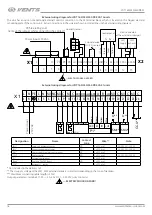
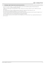
External wiring diagram for VUT 160/250/350 PB EC A14 units
The unit has an option of additional external controls connection to the X2 terminal block, which is located on the hinged electrical
mounting plate of the control unit. Extra connections to the unit are shown in dotted lines in the External wiring diagram.
Power input 230 VAC
1
1
L
2
2
N
3
3
PE PK PK +U
+U
0-10V
4
4
5
6
7
8
9 10 11
12
13
Whit
e
Gr
een
Br
own
Yello
w
External device
NO (CO
2
sensor))
Control panel
- Tx Rx +
Tx Rx
3
2
1
GND
+U
0 -10V
GND
GND
NО C
X1
X2
SM-L SM-N
Humidity sensor
Electric actuators
of the external air dampers
SM1
supply
L1 N
SM2
exhaust
L1 N
PK fire alarm panel
(remove the jumper while connecting the contact)
—ELECTRIC SHOCK HAZARD!
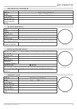
External wiring diagram for VUT 160/250/350 PB EC A21 units
GND
GND
X1
L
L
PE
N
NO
NO
A B
N
NC
C
NO
NO
C
C NO C NO C
+24V
+24V
L N 4 5 6 7 8 9 10 11 12 13 14 15 16 17 18 19 20 21 22 23 24
0-10V
GND
А
В
+24V
1
2
PK1*
1
2
1
2
P1*
1
2
1
2
1
2
C
C
U
*
Boost*
1
2
SM1*
1
2
SM2*
U**
U**
CO2*
GND
0-10V +24V
Brown
Yello
w
Gr
een
W
hit
e
Power input
230 VAC
Designation
Name
Contact
type
Wire**
Note
SМ1*
Supply air damper actuator
NO
2 x 0.75 mm
2
3 A, 30 V DC/~250 AC
SМ2 *
Exhaust air damper actuator
NO
2 x 0.75 mm
2
3 A, 30 V DC/~250 AC
РК1*
Contact from fire alarm control panel
NC
2 x 0.75 mm
2
CCU*
Cooler control
NO
2 x 0.75 mm
2
3 A, 30 V DC/~250 AC
Р1*
External control panel
4 x 0.25 mm
2
Boost*
Contacts ON/OFF Boost
NO
2 x 0.75 mm
2
CO2*
External CO
2
sensor
3 x 0.75 mm
2
* Not included in the delivery set.
** The U supply voltage of the SM1, SM2 external dampers is selected depending on the type of dampers.
*** Maximum connecting cable length is 20 m!
Output parameters: terminals 17-22 — 3 A, 30 V DC / ~ 250 VAC («dry contact»).
— ELECTRIC SHOCK HAZARD!

