background image

20

MAINTENANCE

The unit must undergo technical maintenance 3 to 4 times a year. Maintenance includes general cleaning of the unit and the following 

operations: 

1. Filter maintenance. 

Contaminated fi lters increase air resistance thus impairing supply air delivery into the premises. The fi lters should be cleaned as they get 

dirty, but at least 3-4 times a year. Vacuum cleaning for the air fi lters is allowed.  For new fi lters contact your Seller. 

2. Heat exchanger maintenance.

Even regular technical maintenance of the fi lters may not completely prevent dirt accumulation on the heat exchanger casing. Clean the 

heat exchanger on a regular basis to ensure high heat recovery effi

  ciency. To clean the heat exchanger remove it from the unit and wash with 

warm neutral detergent solution. Re-install the dry heat exchanger into the unit. 

3. Fan maintenance (once a year).

Even regular technical maintenance may not completely prevent dirt accumulation in the fans which reduces the fan capacity and 

impairs supply air delivery into the premises. 

Clean the fans with a soft sloth or a brush. Do not use water, aggressive solvents or sharp objects as they may damage the impeller.

4. Condensate drain check (once a year).

The condensate drain (line) may get clogged by dirt and dust particles contained in the exhaust air. Check the drain line operation by 

fi lling the drain pan under the unit with water, clean the U-trap  and the drain line, if necessary.

5. Fresh air supply duct check (twice a year).

The supply duct grille may get clogged with leaves and other objects reducing the unit performance and supply air delivery. Check the 

supply duct grill twice a year and clean it as required. 

6. Duct system check (every 5 years).

Even regular fulfi lling of all the prescribed above maintenance operations may not completely prevent dirt accumulation in the air ducts 

which reduces the unit capacity. The air duct maintenance includes their periodic cleaning or replacement.

7. Extract shutters and supply diff user cleaning (as required). 

Remove the diff users and louvre shutters and wash those with hot soap water. Do not change the mounting position of the diff users 

and the shutters.

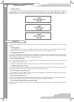
7. Emergency Alarms.

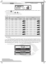
On triggering of either the sensor thermal switch deenergizing the heating elements or in case of fi lter clogging (which triggers the 

diff erential pressure sensor) or communication line damage the unit enters the emergency «Electric heating elements blowing» mode with 
subsequent shutdown in 2 minutes. The red LED goes on, and the control panel displays the message about the malfunction and its origin.

Fault!!!

Heater overheating

Unit OFF

Fault!!!

Filter clogging

Unit OFF

Fault!!!

No communication 

Unit OFF

Summary of Contents for VUT 1000 EH

Page 1: ...VUT 350 EH VUT 500 EH VUT 530 EH VUT 600 EH VUT 800 EH VUT 1000 EH VUT 1500 EH VUT 2000 EH HEAT RECOVERY AIR HANDLING UNIT USER S MANUAL ...

Page 2: ... up Condensate drain Connection to power mains Unit control Maintenance Fault handling Storage and transportation rules Manufacturer s warranty Acceptance certificate Electrical connection certificate Acceptance certificate Seller s information Mounting certificate Warranty card 3 3 3 3 3 6 7 9 10 11 14 20 21 22 22 23 23 23 23 23 24 CONTENT ...

Page 3: ... UNIT IS NOT INTENDED TO BE USED BY CHILDREN PHYSICALLY OR MENTALLY DISABLED PERSONS PERSONS WITH SENSORY DISORDER PERSONS WITH NO APPROPRIATE QUALIFICATION ANY OPERATIONS WITH THE UNIT MUST BE PERFORMED ONLY BY PROPERLY QUALIFIED PERSONNEL AFTER THE APPROPRIATE SAFETY BRIEFING THE UNIT INSTALLATION SITES MUST PREVENT ACCESS BY UNATTENDED CHILDREN Unit 1 item Wall mounted control panel 1 item User...

Page 4: ...E B A Табл 1 Табл 1 Type Dimensions mm A B C D E F G H I K VUT 350 EH 996 403 954 124 1057 554 497 100 119 111 VUT 500 EH 996 403 954 149 1057 554 497 100 119 111 VUT 530 EH 996 403 954 159 1057 554 497 100 119 111 VUT 600 EH 996 403 954 199 1057 554 497 100 119 111 Table 1 ...

Page 5: ...Type Dimensions mm A B C D E F G H I K L M VUT 800 EH 1117 460 1071 249 1176 832 698 613 80 126 154 386 VUT 1000 EH 1117 460 1071 249 1176 832 698 613 80 126 154 386 VUT 1500 EH 1394 581 1345 314 1447 947 814 842 200 394 201 320 VUT 2000 EH 1394 581 1345 314 1447 947 814 842 200 394 201 320 Table 2 ...

Page 6: ...ciency up to 78 up to 88 up to 85 up to 78 up to 77 Heat exchanger type cross flow Heat exchanger material aluminium option SAFETY REQUIREMENTS DO NOT DO NOT OPERATE THE UNIT BEYOND THE SPECIFIED TEMPERATURE RANGE OR IN AN AGGRESSIVE AND EXPLOSIVE MEDIUM DO NOT CONNECT CLOTHES DRYERS OR SIMILAR EQUIPMENT TO THE VENTILATION SYSTEM DO NOT OPERATE THE UNIT IN THE AIR AND DUST MIXTURE MEDIUM DISCONNEC...

Page 7: ...an intake fresh air from outside and warms it up Heat recovery minimizes thermal energy losses energy demand and operating costs for supply air heating accordingly The unit is a framework construction that includes six rigidly fixed 25 mm for the VUT 350 600 EH units and 50 mm for the VUT 800 2000 EH units thick sandwich panels The three layer sandwich panels are made of two galvanized steel sheet...

Page 8: ...h is a safety switch 60 C with automatic reset on temperature dropping back to normal and the other is an emergency switch 90 C with manual reset on pressing the RESET button supply air filter filter class F7 extract air filter filter class G4 Fig 4 Unit design 4 3 12 5 9 13 1 10 7 8 11 2 6 1 7 3 2 11 6 5 8 10 4 12 1 Supply fan 2 Extract filter 3 Heat exchanger 4 Supply filter 5 Extract filter 6 D...

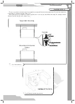
Page 9: ...face Fig 5 While mounting the unit provide the minimum required access to the unit for maintenance and repair The required minimum distances from the unit to the wall is shown in Fig 6 Fig 5 Unit mounting washer nut vibration absorbing rubber nut and lock nut Example Mounting to horizontal surface Suspended mounting Fig 6 Minimum unit mounting distances A 600 mm VUT 350 1000 EH А 850 mm VUT 1500 2...

Page 10: ...ods inside the threaded dowels in the ceiling If the construction rigidity is not sufficient enough it can resonate with the unit and generate abnormal noise and vibration While mounting the unit provide enough service space and an access door for maintenance of the filters heat exchanger and fans One access door is required for each unit For details refer to the outline drawing fig 1 Install anch...

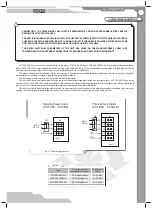
Page 11: ... The unit must be connected to the power mains via an automatic circuit breaker with a magnetic breaker integrated into the house cabling The trip current shall be at least equal to the rated current consumption of the unit see Table 3 and 4 Fig 8 Unit wiring diagrams L N X1 1 2 3 N L QF PE 230 V 50 Hz Unit Ɋȿ 5 4 N N L2 L1 QF PE 400 V 50 Hz L2 L1 X1 2 1 3 L3 L3 Unit Ɋȿ Single phase mains VUT 350 ...

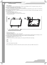
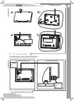
Page 12: ...sing on the ends b Use a screwdriver to disconnect the cable from the terminal block c Disconnect the data cable Fig 9 Control panel disconnection a b Attach the cable as necessary Assemble the control panel a Route the cable through the access hole in the bottom lid b Fix the control panel bottom lid where desired and ensure a secure fit of the lid to the wall by tightening the self tapping screw...

Page 13: ...onnections on the controller circuit board see Fig 11 Fig 11 Connection to controller circuit board Terminal block on the panel yellow green В brown А white Data cable Outdoor air t sensor connector Supply air t sensor connector 1 2 3 4 Controller circuit board terminal block yellow 1 green 2 brown 3 white 4 CONTROLLER CIRCUIT BOARD WALL MOUNTED CONTROL PANEL ...

Page 14: ...t time 2 normal ventilation speed 3 intensive ventilation mode when extra air supply is required The temperature sensors enable optimum operation mode selection by the system in order to maintain pre set temperature in the air duct The control panel is equipped with a temperature sensor thereby enabling maintaining of the set user defined indoor temperature at the selected fan speed or in accordan...

Page 15: ... operating logic is required to enable heat removal from the electric heating elements and prevent sensor thermal switch activation The unit is turned off in 2 minutes 3 Unit Activation Deactivation Connect the unit to the power mains 1 230 V 50 Hz for VUT 350 600 EH units or 3 400 V 50 Hz for VUT 800 2000 EH units For details refer to connection to power mains Page 11 The indicator displays the V...

Page 16: ...cuit To select a control mode press the or button from the main operation window This will invoke Duct or Room controlled temperature on the display The Room mode enables air temperature control on the premises using the readings from the control panel integral sensor The Duct mode enables air temperature control in the supply air duct using the readings from the supply duct sensor Fig 13 and 14 F...

Page 17: ...eps the time even while the unit is off The battery has 2 3 years of useful life To replace the battery open the control panel casing by pressing the ends Use the button to select a user defined entry year month date day hour minute Change the selected entry by pressing and buttons Speed stage Changing the fan speed and buttons The main menu enables the user to change the critical unit operation p...

Page 18: ...gnalling the Day timer operation To change the user defined position activation time deactivation time hours and minutes press the button Press the and buttons to modify the selected entry The factory settings for the Day timer are Turning ON time 06 30 Turning OFF time 23 30 Filter replacement message The reminder message pops up periodically for a brief time replacing the main operation window t...

Page 19: ...inutes closed 25 minutes which disables the heat exchanger freezing In the No Heat Recovery mode Summer mode the bypass damper is constantly open Toselecttheuser definedposition dayoftheweek timerstatusontheday on off unitoperationtimeinthemode controlledtemperature and fan speed use the button To change the selected entry press and buttons Table 5 Day State Interval 1 Interval 2 Activation Time D...

Page 20: ...t clogged by dirt and dust particles contained in the exhaust air Check the drain line operation by filling the drain pan under the unit with water clean the U trap and the drain line if necessary 5 Fresh air supply duct check twice a year The supply duct grille may get clogged with leaves and other objects reducing the unit performance and supply air delivery Check the supply duct grill twice a y...

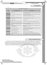
Page 21: ...en Check the heat exchanger condition Turn the unit off and restart it after the freeze danger is no longer imminent The electric heater malfunction Contact the service centre High noise vibration The impeller s are soiled Clean the impeller s The screw connection is too loose Tighten the screw connection against stop No anti vibration dampers Install anti vibration mounts not included into the de...

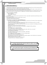
Page 22: ...details stated on the unit packing and in the user s manual User s failure to ensure timely technical maintenance of the unit External damage to the casing excluding external modifications of the unit as required for its installation and the internal components of the unit Alteration of the unit design or engineering changes of the unit Replacement and use of the unit assemblies parts and componen...

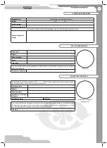
Page 23: ...nician s full name Installation date Signature Shop name Address Phone number E mail Sales date This is to certify delivery of the complete unit with the user s manual The warranty terms are acknowl edged and accepted Customer s signature ACCEPTANCE CERTIFICATE SELLER S INFORMATION MOUNTING CERTIFICATE Seller s seal Installation technician s company seal This is to certify that the work specific t...

Page 24: ...24 Product type Air handling unit with heat recovery Model VUT__________EH Serial number Manufacturing date Sales date Warranty period Sales company Seller s seal WARRANTY CARD ...

Page 25: ...V28EN 04 ...
Reviews: