10
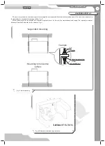
The unit must be connected to sewage collection system, fi g. 7. Connect the pipe, U-trap (not included in delivery package) and
sewage collection system with metal, plastic or rubber connecting pipes, fi g. 7. The pipe slope downwards must be at least 3°. Fill up
the system with water before connecting the unit to the power mains! The U-trap must be fi lled with water at all times during the unit
operation. Make sure that the water fl ows freely into the sewage collection system or otherwise condensed water may build up in the
unit during heat recovery.
The condensate drainage system is designed for normal operation in premises with air temperatures above 0 °C. If the expected air
temperatures are below 0 °C the condensate drainage system must be equipped with heat insulation and pre-heating facilities.
CONDENSATE DRAINAGE
Fig. 7. Condensate drainage
min 3
°
drain pipe
U-trap
sewage system
tube
tube
min 3°
Precautions:
The unit is designed for mounting on a rigid and stable structure in compliance to the technical data and unit weight.
The unit is mounted with anchor bolts. Make sure that a mounting construction has suffi
cient load capacity for the unit weight.
Otherwise reinforce an installation place by beams, etc. Then insert threaded rods inside the threaded dowels in the ceiling. If the
construction rigidity is not suffi
cient enough it can resonate with the unit and generate abnormal noise and vibration.
While mounting the unit provide enough service space and an access door for maintenance of the fi lters, heat exchanger and fans.
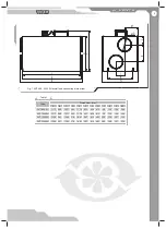
One access door is required for each unit. For details, refer to the outline drawing, fi g. 1.
Install anchor bolts M8 into the fi xation for the ceiling suspension mount and fi x it with nuts and washers.
Make sure the unit casing has no foreign objects inside, like paper and foil.
If the threaded bolts used for the unit mounting are too short the unit can generate abnormal noise and resonate with the ceiling.
If the unit connection place to the spiral seam duct is supposed to be the source of the abnormal noise, replace the spiral air duct with
a fl exible air duct. The precautions referred above are normally suffi
cient to solve the resonance problem.
The fl exible connectors may be also installed to troubleshoot the resonating problem.
To attain the best performance of the unit while mounting provide a straight 1 m duct section on both sides of the unit.
Access to the unit must be prevented by installing a protecting grille or any other device with the mesh width up to 12.5 mm.
DO NOT CONNECT SEVERAL DRAIN PIPES FROM SEVERAL AIR HANDLING UNITS TO ONE U-TRAP!
DIRECT CONDENSATE OUTSIDE WITHOUT CONNECTION TO DRAIN SYSTEM IS NOT ALLOWED!
Summary of Contents for VUT 1000 EH
Page 25: ...V28EN 04 ...


