background image

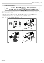
The technical maintenance includes periodic cleaning of the surfaces from accumulated dust and dirt. The impeller blades require 
thorough cleaning once in 6 months. 

The fan surfaces need to be cleaned of dirt and dust regularly by using a soft, wet cloth and mild detergent (Pic. 21-24).
Do not allow liquids to come in contact with the electric motor. Wipe surfaces dry after cleaning.

Perform all the above operations in the reverse order after cleaning. 

22

21

23

24

QF

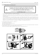
TECHNICAL MAINTENANCE

DISCONNECT THE UNIT FROM POWER SUPPLY BEFORE ANY MAINTENANCE 

OPERATIONS!

MAKE SURE THE UNIT IS DISCONNECTED FROM POWER MAINS BEFORE REMOVING THE 

PROTECTION

11

vents-us.com

Summary of Contents for VKP 100

Page 1: ...USER S MANUAL Inline centrifugal fan VKP VKPF...

Page 2: ...nty card 15 This user s manual is a main operating document intended for technical maintenance and operating staff The manual contains information about purpose technical details operating principle d...

Page 3: ...While mounting the unit avoid compression of the casing Deformation of the casing may result in motor jam and excessive noise Misuse of the unit and any unauthorised modifications are not allowed Do...

Page 4: ...g rules for design of electrical units and has a contact separation in all poles that allows for full disconnection under overvoltage category III conditions If the supply cord is damaged it must be r...

Page 5: ...thhighrequirements to the noise level and with limited space for mounting The unit is rated for continuous operation The unit is a component part and is not designed for stand alone operation Transpor...

Page 6: ...0 27 3 7 104 98 94 89 84 77 69 61 52 43 33 1 2 120 60 VKP 125 5 66 0 54 4 2 220 214 208 202 196 190 184 178 172 160 150 2 4 120 60 VKP 125 125x2 5 5 74 0 61 4 2 244 234 223 213 204 194 183 170 160 150...

Page 7: ...urved blades fixed to a flange The terminal box with an operating capacitor and a terminal box inside is attached to the casing end face The flange with the turbine and the fixing bracket with mountin...

Page 8: ...qual to 1 air duct diameter on intake side and to 3 air duct diameters on outlet side No filters or any other similar devices are allowed to be installed in these sections CAUTION If necessary close t...

Page 9: ...insulated flexible duct between any exhaust grill and fan for low noise level Flexible duct should be connected to the fan with hose clamps VENTS C series is recommended aluminum foil tape or both Al...

Page 10: ...it breaker installation place must provide quick access for emergency shutdown of the unit The trip current of the automatic circuit breaker QF must exceed the maximum current consumption of the unit...

Page 11: ...y using a soft wet cloth and mild detergent Pic 21 24 Do not allow liquids to come in contact with the electric motor Wipe surfaces dry after cleaning Perform all the above operations in the reverse o...

Page 12: ...off the fan Troubleshoot the motor jamming Restart the fan Circuit breaker tripping during the fan start Excessive electric current consumption caused by a short circuit Turn off the fan Contact the...

Page 13: ...and storage operations to prevent possible damage to the unit Follow the handling requirements applicable for the particular type of cargo The unit can be carried in the original packaging by any mod...

Page 14: ...ended installation instructions Labor to remove and replace products is not covered The duration of any implied warranty is limited to the time period specified for the express warranty Some states do...

Page 15: ..._____________________ unit is installed pursuant to the requirements stated in the present user s manual Installation Stamp Company name Address Phone Number Installation Technician s Full Name Instal...

Page 16: ...VUSA17EN 06...

Reviews: