background image

13

www.vents-us.com

PROBLEM

POSSIBLE REASONS

TROUBLESHOOTING

The fan will not start on power-up.

No electric power.

Check the electrical connections and the power 
switch status. 

Motor jamming.

Switch off the fan. Eliminate the cause for the impeller 
clogging. Switch the fan back on.

The automatic breaker activates 
upon the unit power-up.

The automatic circuit breaker is 
triggered by abnormally high current 
consumption due to a short circuit.

Disconnect the fan from the power mains and 
contact the Seller.
Do not switch on the fan again!

Low air flow.

Clogging of air ducts or other ventilation 
system elements due to contamination. 
Impeller contamination. 
Damaged air ducts. Closed air dampers.

Clean the air ducts and other ventilation system 
elements as well as the impeller. Check the air ducts 
for damage. Make sure that the air dampers and 
louvers are open.

If the malfunction is too complex to be eliminated on the spot, contact the fan Seller. 

STORAGE AND TRANSPORTATION REGULATIONS

•  Store the unit in the manufacturer’s original packaging box in a dry closed ventilated premise with temperature range +41˚F...+104 ˚F 

and relative humidity up to 70 %.

•  Storage environment must not contain aggressive vapors and chemical mixtures provoking corrosion, insulation, and sealing 

deformation.

•  Use suitable hoist machinery for handling and storage operations to prevent possible damage to the unit.
•  Follow the handling requirements applicable for the particular type of cargo.
•  The unit can be carried in the original packaging by any mode of transport provided proper protection against precipitation and 

mechanical damage. The unit must be transported only in the working position.

•  Avoid sharp blows, scratches, or rough handling during loading and unloading.
•  Prior to the initial power-up after transportation at low temperatures, allow the unit to warm up at operating temperature for at least 

3-4 hours.

TROUBLESHOOTING

Summary of Contents for OV1 200

Page 1: ...USER S MANUAL Electric axial fans OV1 OVK1 VKOM...

Page 2: ...has a contact separation in all poles that allows for full disconnection under overvoltage category III conditions CAUTION In order to avoid a safety hazard due to inadvertent resetting of the thermal...

Page 3: ...eck the unit for any visible damage of the impeller the casing and the grille before starting installation The casing internals must be free of any foreign objects that can damage the impeller blades...

Page 4: ...ances fibrous materials coarsedust sootandoilparticlesorenvironmentsfavorablefortheformationofhazardoussubstances toxicsubstances dust pathogenic germs The unit is rated as a Class I electrical applia...

Page 5: ...2 5 8 5 1 2 OV1 315 12 5 16 3 8 16 15 16 14 15 16 6 11 16 OV1 Model Measurements in D D1 D2 d L OVK1 200 8 3 16 10 5 8 11 13 16 1 4 4 3 4 OVK1 250 10 5 16 13 14 3 16 1 4 5 1 2 OVK1 315 12 5 16 15 3 88...

Page 6: ...d with bolts 4 The motor and impeller 5 are mounted on a bracket inside the casing The fans are equipped with a terminal box with a cable for remote connection OV1 OVK1 3 4 1 2 5 3 4 1 2 5 VKOM fan Th...

Page 7: ...nance technical service and replacement operations When the service conditions may lead to water ingress the fans must be equipped with adequate protection For example the fans may be installed under...

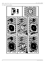
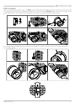
Page 8: ...8 OV1 OVK1 VKOM www vents us com OV1 and OVK1 fan installation...

Page 9: ...ed with clamps The power is supplied via terminal box on the fan casing The VKOM z delivery set includes mounting brackets for attaching the unit to the mounting surface Depending on a delivery set tw...

Page 10: ...short circuit The position of the external automatic circuit breaker must ensure free access for quick power off of the unit The trip current of the automatic circuit breaker must exceed the maximum c...

Page 11: ...11 www vents us com OV1 OVK1 fan connection VKOM fan connection...

Page 12: ...ater penetration onto the electric motor Wipe the cleaned surfaces dry To carry out technical maintenance of the VKOM fans remove the fans from the duct by undoing the retaining bolts on the units or...

Page 13: ...open If the malfunction is too complex to be eliminated on the spot contact the fan Seller STORAGE AND TRANSPORTATION REGULATIONS Store the unit in the manufacturer s original packaging box in a dry...

Page 14: ...any implied warranty is limited to the time period specified for the express warranty Some states do not allow limitations on how long an implied warranty lasts so the above limitation may not apply t...

Page 15: ...e _____________________________________ unit is installed pursuant to the requirements stated in the present user s manual Installation Stamp Company name Address Phone Number Installation Technician...

Page 16: ...VUSA03EN 13...

Reviews: